| This article needs additional citations for verification. Please help improve this article by adding citations to reliable sources. Unsourced material may be challenged and removed. Find sources: "Reticle" – news · newspapers · books · scholar · JSTOR (February 2009) (Learn how and when to remove this message) |


A reticle, or reticule also known as a graticule, is a pattern of fine lines or markings built into the eyepiece of an optical device such as a telescopic sight, spotting scope, theodolite, optical microscope or the screen of an oscilloscope, to provide measurement references during visual inspections. Today, engraved lines or embedded fibers may be replaced by a digital image superimposed on a screen or eyepiece. Both terms may be used to describe any set of patterns used for aiding visual measurements and calibrations, but in modern use reticle is most commonly used for weapon sights, while graticule is more widely used for non-weapon measuring instruments such as oscilloscope display, astronomic telescopes, microscopes and slides, surveying instruments and other similar devices.
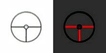
There are many variations of reticle pattern; this article concerns itself mainly with the most rudimentary reticle: the crosshair. Crosshairs are typically represented as a pair of perpendicularly intersecting lines in the shape of a cross, "+", though many variations of additional features exist including dots, posts, concentric circles/horseshoes, chevrons, graduated markings, or a combination of above. Most commonly associated with telescopic sights for aiming firearms, crosshairs are also common in optical instruments used for astronomy and surveying, and are also popular in graphical user interfaces as a precision pointer. The reticle is said to have been invented by Robert Hooke, and dates to the 17th century. Another candidate as inventor is the amateur astronomer William Gascoigne, who predated Hooke.
The term reticle comes from the Latin reticulum, meaning small net.
Uses
Firearms
Telescopic sights for firearms, generally just called scopes, are probably the device most often associated with crosshairs. Motion pictures and the media often use a view through crosshairs as a dramatic device, which has given crosshairs wide cultural exposure.
Reticle shape
While the traditional thin crossing lines are the original and still the most familiar cross-hair shape, they are really best suited for precision aiming at high contrast targets, as the thin lines are easily lost in complex backgrounds, such as those encountered while hunting. Thicker bars are much easier to discern against a complex background, but lack the precision of thin bars. The most popular types of cross-hair in modern scopes are variants on the duplex cross-hair, with bars that are thick on the perimeter and thin out in the middle. The thick bars allow the eye to quickly locate the center of the reticle, and the thin lines in the center allow for precision aiming. The thin bars in a duplex reticle may also be designed to be used as a measure. Called a 30/30 reticle, the thin bars on such a reticle span 30 minutes of arc (0.5º), which is approximately equal to 30 inches at 100 yards or 90 centimeters at 100 meters. This enables an experienced shooter to deduce, on the basis of the known size of an object in view, (as opposed to guess or estimate) the range within an acceptable error limit.
Wire crosshairs

Originally crosshairs were constructed out of hair or spiderweb, these materials being sufficiently thin and strong. Many modern scopes use wire crosshairs, which can be flattened to various degrees to change the width. These wires are usually silver in color, but appear black when backlit by the image passing through the scope's optics. Wire reticles are by nature fairly simple, as they require lines that pass all the way across the reticle, and the shapes are limited to the variations in thickness allowed by flattening the wire; duplex crosshairs, and crosshairs with dots are possible, and multiple horizontal or vertical lines may be used. The advantage of wire crosshairs is that they are fairly tough and durable, and provide no obstruction to light passing through the scope.
Etched reticles

The first suggestion for etched glass reticles was made by Philippe de La Hire in 1700. His method was based on engraving the lines on a glass plate with a diamond point. Many modern crosshairs are actually etched onto a thin plate of glass, which allows a far greater latitude in shapes. Etched glass reticles can have floating elements, which do not cross the reticle; circles and dots are common, and some types of glass reticles have complex sections designed for use in range estimation and bullet drop and drift compensation (see external ballistics). A potential disadvantage of glass reticles is that the surface of the glass reflects some light (about 4% per surface on uncoated glass) lessening transmission through the scope, although this light loss is near zero if the glass is multicoated (coating being the norm for all modern high quality optical products).
Illuminated reticles
Reticles may be illuminated, either by a plastic or fiber optic light pipe collecting ambient light or, in low light conditions, by a battery powered LED. Some sights also use the radioactive decay of tritium for illumination that can work for 11 years without using a battery, used in the British SUSAT sight for the SA80 (L85) assault rifle and in the American ACOG (Advanced Combat Optical Gunsight). Red is the most common color used, as it is the least destructive to the shooter's night vision, but some products use green or yellow illumination, either as a single colour or changeable via user selection.
Graticule
Another term for reticle is graticule, which is frequently encountered in British and British military technical manuals. It came into common use during World War I.
Reticle focal plane
The reticle may be located at the front or rear focal plane (First Focal Plane (FFP) or Second Focal Plane (SFP)) of the telescopic sight. On fixed power telescopic sights there is no significant difference, but on variable power telescopic sights the front plane reticle remains at a constant size compared to the target, while rear plane reticles remain a constant size to the user as the target image grows and shrinks. Front focal plane reticles are slightly more durable, but most American users prefer that the reticle remains constant as the image changes size, so nearly all modern American variable power telescopic sights are rear focal plane designs. American and European high end optics manufacturers often leave the customer the choice between a FFP or SFP mounted reticle.
Collimated reticles

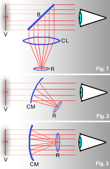
Collimated reticles are produced by non-magnifying optical devices such as reflector sights (often called reflex sights) that give the viewer an image of the reticle superimposed over the field of view, and blind collimator sights that are used with both eyes. Collimated reticles are created using refractive or reflective optical collimators to generate a collimated image of an illuminated or reflective reticle. These types of sights are used on surveying/triangulating equipment, to aid celestial telescope aiming, and as sights on firearms. Historically they were used on larger military weapon systems that could supply an electrical source to illuminate them and where the operator needed a wide field of view to track and range a moving target visually (i.e. weapons from the pre laser/radar/computer era). More recently sights using low power consumption durable light emitting diodes as the reticle (called red dot sights) have become common on small arms with versions like the Aimpoint CompM2 being widely fielded by the U.S. Military.
Holographic reticles
Holographic weapon sights use a holographic image of a reticle at finite set range built into the viewing window and a collimated laser diode to illuminate it. An advantage to holographic sights is that they eliminate a type of parallax problem found in some optical collimator based sights (such as the red dot sight) where the spherical mirror used induces spherical aberration that can cause the reticle to skew off the sight's optical axis. The use of a hologram also eliminates the need for image dimming narrow band reflective coatings and allows for reticles of almost any shape or mil size. A downside to the holographic weapon sight can be the weight and shorter battery life. As with red dot sights, holographic weapon sights have also become common on small arms with versions like the Eotech 512.A65 and similar models fielded by the U.S. Military and various law enforcement agencies.
Surveying and astronomy
In older instruments, reticle crosshairs and stadia marks were made using threads taken from the cocoon of the brown recluse spider. This very fine, strong spider silk makes for an excellent crosshair.
Surveying
In surveying, reticles are designed for specific uses. Levels and theodolites would have slightly different reticles. However, both may have features such as stadia marks to allow distance measurements.
Astronomy
For astronomical uses, reticles could be simple crosshair designs or more elaborate designs for special purposes. Telescopes used for polar alignment could have a reticle that indicates the position of Polaris relative to the north celestial pole. Telescopes that are used for very precise measurements would have a filar micrometer as a reticle; this could be adjusted by the operator to measure angular distances between stars.
For aiming telescopes, reflex sights are popular, often in conjunction with a small telescope with a crosshair reticle. They make aiming the telescope at an astronomical object easier.
The constellation Reticulum was designated to recognize the reticle and its contributions to astronomy.
See also
- Adrien Auzout
- Deflection (ballistics)
- Focusing screen – used in photography, and often etched
- Iron sight
- List of astronomical instruments
- Photomask – partial plate with holes or transparencies used in photolithography integrated circuit fabrication is also called a "reticle"
- Sniper
- Target blip
- Parallax
References
- A Christopher Gorse, David Johnston, Martin Pritchard, Dictionary of Construction, Surveying and Civil Engineering (2 ed.), Oxford University Press, 2020 – reticule
- dictionary.com – reticule
- McIntyre, Thomas (2007). The Field & Stream Hunting Optics Handbook. Globe Pequot. p. 118.
- Sellers, David. "Serendipity and a Spider William Gascoigne (c.1612-44) and the Invention of the Telescope Micrometer". magavelda. Retrieved 4 November 2019.
- Maurice Daumas, Scientific Instruments of the Seventeenth and Eighteenth Centuries and Their Makers, Portman Books, London 1989 ISBN 978-0-7134-0727-3
- Richard Feynman, the red books
- Glazebrook, Sir Richard, A Dictionary of Applied Physics, Macmillan and Co., London, 1923.
- "First vs Second Focal Plane – What is the Differences?". 25 July 2022.
- "Holographic Sights for SOCOM M4s". Retrieved 30 August 2012.
- Raymond Davis, Francis Foote, Joe Kelly, Surveying, Theory and Practice, McGraw-Hill Book Company, 1966 LC 64-66263
- Berenbaum, May R., Field Notes - Spin Control, The Sciences, The New York Academy Of Sciences, September/October 1995