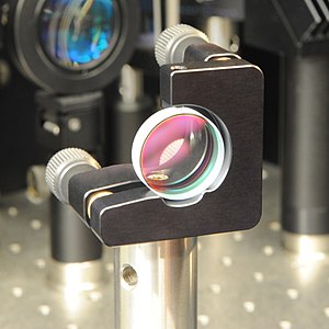
A dielectric mirror, also known as a Bragg mirror, is a type of mirror composed of multiple thin layers of dielectric material, typically deposited on a substrate of glass or some other optical material. By careful choice of the type and thickness of the dielectric layers, one can design an optical coating with specified reflectivity at different wavelengths of light. Dielectric mirrors are also used to produce ultra-high reflectivity mirrors: values of 99.999% or better over a narrow range of wavelengths can be produced using special techniques. Alternatively, they can be made to reflect a broad spectrum of light, such as the entire visible range or the spectrum of the Ti-sapphire laser.
Dielectric mirrors are very common in optics experiments, due to improved techniques that allow inexpensive manufacture of high-quality mirrors. Examples of their applications include laser cavity end mirrors, hot and cold mirrors, thin-film beamsplitters, high damage threshold mirrors, and the coatings on modern mirrorshades and some binoculars roof prism systems.
Mechanism

The reflectivity of a dielectric mirror is based on the interference of light reflected from the different layers of a dielectric stack. This is the same principle used in multi-layer anti-reflection coatings, which are dielectric stacks which have been designed to minimize rather than maximize reflectivity. Simple dielectric mirrors function like one-dimensional photonic crystals, consisting of a stack of layers with a high refractive index interleaved with layers of a low refractive index (see diagram). The thicknesses of the layers are chosen such that the path-length differences for reflections from different high-index layers are integer multiples of the wavelength for which the mirror is designed. The reflections from the low-index layers have exactly half a wavelength in path length difference, but there is a 180-degree difference in phase shift at a low-to-high index boundary, compared to a high-to-low index boundary, which means that these reflections are also in phase. In the case of a mirror at normal incidence, the layers have a thickness of a quarter wavelength.

Other designs have a more complicated structure generally produced by numerical optimization. In the latter case, the phase dispersion of the reflected light can also be controlled (a chirped mirror). In the design of dielectric mirrors, an optical transfer-matrix method can be used. A well-designed multilayer dielectric coating can provide a reflectivity of over 99% across the visible light spectrum.
Dielectric mirrors exhibit retardance as a function of angle of incidence and mirror design.
As shown in the GIF, the transmitted color shifts towards the blue with increasing angle of incidence. Regarding interference in the high reflective index medium this blueshift is given by the formula
- ,
where is any multiple of the transmitted wavelength and is the angle of incidence in the second medium. See thin-film interference for a derivation. However, there is also interference in the low refractive index medium. The best reflectivity will be at
- ,
where is the transmitted wavelength under perpendicular angle of incidence and
- .
Manufacturing

The manufacturing techniques for dielectric mirrors are based on thin-film deposition methods. Common techniques are physical vapor deposition (which includes evaporative deposition and ion beam assisted deposition), chemical vapor deposition, ion beam deposition, molecular beam epitaxy, sputter deposition, and sol-gel deposition. Common materials are magnesium fluoride (n = 1.37), silicon dioxide (n = 1.45), tantalum pentoxide (n = 2.28) , zinc sulfide (n = 2.32), and titanium dioxide (n = 2.4).
Polymeric dielectric mirrors are fabricated industrially via co-extrusion of melt polymers, and by spin-coating or dip-coating on smaller scale.
See also
References
- Slaiby, ZenaE.; Turki, Saeed N. (November–December 2014). "Study the reflectance of dielectric coating for the visiblespectrum". International Journal of Emerging Trends & Technology in Computer Science. 3 (6): 1–4. ISSN 2278-6856. Retrieved 2024-08-12.
- Apfel, J. H. (1982). "Phase retardance of periodic multilayer mirrors". Applied Optics. 21 (4): 733–738. Bibcode:1982ApOpt..21..733A. doi:10.1364/AO.21.000733. PMID 20372527.
- E, Huett (April 26, 2022). "Determination of 2D Plasma Parameters with Filtered Cameras. An Application to the X-Point Radiator Regime in ASDEX Upgrade". Max-Planck-Institut für Plasmaphysik. doi:10.17617/2.3379034.
- Bertucci, Simone; Megahd, Heba; Dodero, Andrea; Fiorito, Sergio; Di Stasio, Francesco; Patrini, Maddalena; Comoretto, Davide; Lova, Paola (2022-05-04). "Mild Sol–Gel Conditions and High Dielectric Contrast: A Facile Processing toward Large-Scale Hybrid Photonic Crystals for Sensing and Photocatalysis". ACS Applied Materials & Interfaces. 14 (17): 19806–19817. doi:10.1021/acsami.1c23653. ISSN 1944-8244. PMC 9073830. PMID 35443778.
- Comoretto, Davide, ed. (2015). Organic and Hybrid Photonic Crystals. doi:10.1007/978-3-319-16580-6. ISBN 978-3-319-16579-0. S2CID 139074878.
- Lova, Paola; Giusto, Paolo; Stasio, Francesco Di; Manfredi, Giovanni; Paternò, Giuseppe M.; Cortecchia, Daniele; Soci, Cesare; Comoretto, Davide (9 May 2019). "All-polymer methylammonium lead iodide perovskite microcavities". Nanoscale. 11 (18): 8978–8983. doi:10.1039/C9NR01422E. hdl:11567/944564. ISSN 2040-3372. PMID 31017152. S2CID 129943931.
- Russo, Manuela; Campoy-Quiles, Mariano; Lacharmoise, Paul; Ferenczi, Toby A. M.; Garriga, Miquel; Caseri, Walter R.; Stingelin, Natalie (2012). "One-pot synthesis of polymer/inorganic hybrids: toward readily accessible, low-loss, and highly tunable refractive index materials and patterns". Journal of Polymer Science Part B: Polymer Physics. 50 (1): 65–74. Bibcode:2012JPoSB..50...65R. doi:10.1002/polb.22373. ISSN 1099-0488.
 medium this blueshift is given by the formula
 ,
, is any multiple of the transmitted wavelength and
  is the angle of incidence in the second medium.
See
  ,
, is the transmitted wavelength under perpendicular angle of incidence and
 .
.