| [REDACTED] | |
| International standard | EN 50090, ISO/IEC 14543 |
|---|---|
| Industry | Building automation |
| Website | knx |


KNX is an open standard (see EN 50090, ISO/IEC 14543) for commercial and residential building automation. KNX devices can manage lighting, blinds and shutters, HVAC, security systems, energy management, audio video, domestic appliances, displays, remote control, etc. KNX evolved from three earlier standards; the European Home Systems Protocol (EHS), BatiBUS, and the European Installation Bus (EIB or Instabus).
It can use twisted pair (in a tree, line or star topology), powerline, RF, or IP links. On this network, the devices form distributed applications and tight interaction is possible. This is implemented via interworking models with standardised datapoint types and objects, modelling logical device channels.
Standard
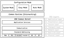
The KNX standard has been built on the OSI-based EIB communication stack extended with the physical layers, configuration modes and application experience of BatiBUS and EHS.
KNX installations can use several physical communication media:
- Twisted pair wiring (TP1 Cable) (inherited from the EIB standard). (The previously inherited BatiBUS communication medium (TP0) is no longer part of the KNX Specifications.)
- Power-line networking (inherited from EIB standard). (The previously inherited EHS communication medium (PL132) is no longer part of the KNX Specifications.)
- Radio (KNX-RF)
- IP (also referred to as EIBnet/IP or KNXnet/IP)
KNX is not based on a specific hardware platform and a network can be controlled by anything from an 8-bit microcontroller to a PC, according to the demands of a particular building. The most common form of installation is over twisted pair medium.
KNX is an approved standard by the following organisations, (inter alia):
- International standard (ISO/IEC 14543-3)
- European standard (CENELEC EN 50090 and CEN EN 13321–1)
- US standard (ANSI/ASHRAE 135)
- China Guobiao (GB/T 20965)
It is administered by the KNX Association cvba, a non-profit organisation governed by Belgian law which was formed in 1999. The KNX Association had 500 registered hardware and software vendor members from 45 nations as at 1 July 2021. It had partnership agreements with 100,000 installer companies in 172 countries and more than 500 registered training centres. This is a royalty-free open standard and thus access to the KNX specifications is unrestricted.
Architecture
KNX devices are commonly connected by a twisted pair bus and can be modified from a controller. The bus is routed in parallel to the electrical power supply to all devices and systems on the network linking:
- Sensors (e.g. push buttons, thermostats, anemometers, movement) gather information and send it on the bus as a data telegram;
- Actuators (dimming units, heating valves, displays) receive data telegrams which are then converted into actions; and
- Controllers and other logic functions (room temperature controllers, shutter controllers and other)
- System devices and components (e.g. line couplers, backbone couplers).
Classifying devices as either "sensor" or "actuator" is outdated and simplistic. Many actuators include controller functionality, but also sensor functionality (for instance measuring operating hours, number of switch cycles, current, electrical power consumption, and more).
Application software, together with system topology and commissioning software, is loaded onto the devices via a system interface component. Installed systems can be accessed via LAN, point to point links, or phone networks for central or distributed control of the system via computers, tablets and touch screens, and smartphones.

The key features of the KNX architecture are:
- Interworking and distributed application models for the building automation various tasks;
- Schemes for configuration and management of resources on the network, and to permit the binding of parts of a distributed application in different nodes;
- A communication system with a message protocol and models for the communication stack in each node (capable of hosting distributed applications (KNX Common Kernel); and
- Models for the realization of these elements when developing actual devices to be mounted and linked in an installation.
Applications, interworking and binding
Central to the KNX architecture concepts are datapoints (inputs, outputs, parameters, and diagnostic data) which represent process and control variables in the system. The standardised containers for these datapoints are group objects and interface object properties. The communication system offers a reduced instruction set to read and write datapoint values. Datapoints have to conform to standardised datapoint types, themselves grouped into functional blocks. These functional blocks and datapoint types are related to applications fields, but some of them are of general use (such as date and time). Datapoints may be accessed through unicast or multicast mechanisms.
To logically link applications' datapoints across the network, KNX has three underlying binding schemes: one for free, one for structured and one for tagged binding:
- In free binding, links between datapoints are not prescribed - in combination with free addressing, this supports customized multicast grouping at the level of individual datapoints and is central to S-mode configuration (see below);
- In structured binding, the KNX specification stipulates a precise pattern for linking a whole set of datapoints, usually corresponding to a Functional Block or Channel (push-button modes follow this concept);
- Tagged binding is also pre-structured by the application models, but the numerical value of address is part of its value.
Kernel and message protocol
The common kernel sits on top of the physical layers and the medium-specific data link layer and is shared by all the devices on the KNX Network. It is OSI 7-layer model compliant:
- A general data link layer, which sits above the specific data link layers for each medium, provides access control and the logical link control;
- A network layer (for nodes with routing functionality) provides a segment-wise acknowledged telegram (frame) and controls the hop count of a frame;
- A transport layer enables four types of communication: one-to-many connectionless (multicast), one-to-all connectionless (broadcast), one-to-one connectionless, one-to-one connection-oriented;
- (OSI session and presentation layers are empty); and
- An application layer offers a toolkit of services to the application process.
Configuration modes
An installation has to be configured at the network topology level and at individual nodes or devices. The first level is a precondition or “bootstrap” phase, prior to the configuration of the distributed applications, i.e. binding and parameter setting. Configuration may be achieved through a combination of local activity on the devices (such pushing a button), and active network management communication over the bus (peer-to-peer, or more centralized master-slave).
The KNX configuration mode:
- picks out a certain scheme for configuration and binding;
- maps it to a particular choice of address scheme; and
- completes all this with a choice of management procedures and matching resource realizations.
Some modes require more active management over the bus, whereas some others are mainly oriented towards local configuration. There are three categories of KNX devices:
- A-mode or "Automatic mode" devices which can configure themselves, and are able to be installed by the end user;
- E-mode or "Easy mode" devices that require basic training to install: their behaviour is pre-programmed, but configuration parameters need to be tailored to the user's requirements; or
- S-mode or "System mode" devices that can be used to create sophisticated building automation systems: they have no default behaviour, and must be programmed and installed by specialists.
KNX encompasses tools for project engineering tasks such as linking a series of individual devices into a functioning installation and integrating different media and configuration modes. This is embodied in an Engineering Tool Software (ETS) suite.
Devices
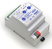
A KNX installation always consists of a set of devices connected to the bus or network. Device models vary according to node roles, capabilities, management features and configuration modes, and are all laid down in the profiles. There are also general-purpose device models, such as for bus coupling units (BCUs) or bus interface modules (BIMs).
Devices may be identified and subsequently accessed throughout the network either by their individual address, or by their unique serial number, depending on the configuration mode. (Unique serial numbers are allocated by the KNX Association Certification Department.) Devices can also disclose both a manufacturer specific reference and functional (manufacturer independent) information when queried.
Topology and addressing
A KNX wired network can be formed with tree, line and star topologies, which can be mixed as needed; ring topologies are not supported. A tree topology is recommended for a large installation.
KNX can link up to 57,375 devices using 16-bit addresses.
- The lowest eight bits provide up to 256 addresses within one line, which can consist of up to four segments, each having a maximum of 64 (TP1-64) devices, or up to 256 (TP1-256) devices. Each segment requires a local power supply and the maximum length of a segment is 1000 m. (The actual number of devices supported is dependent on the power supply and the power load of the individual devices.) Segments connected with line repeaters can extend to a length of 4000 m and link up to 256 devices.
- Lines may be grouped together into an area, with up to 15 lines connected to a main line via line couplers. The next four bits of the address are used to identify individual lines.
- An entire domain can be formed with 15 areas linked by a backbone line using backbone couplers, and the top four bits of the address space identify an area. (Line repeaters may not be used on a backbone or mainline.)
Coupling units allow address filtering which helps to improve performance given the limited bus signal speed. An installation based on KNXnet/IP allows the integration of KNX sub networks via IP as the KNX address structure is similar to an IP address.
Physical layer
TP 1
The TP1 twisted pair bus (inherited from EIB) provides asynchronous, character oriented data transfer and half-duplex bidirectional differential signaling with a signaling speed of 9600 bit/s. Media access control is via CSMA/CA. Every bus user has equal data transmission rights and data is exchanged directly (peer-to-peer) between bus users. SELV power is distributed via the same pair for low-power devices. A deprecated specification, TP0, running at a slower signalling speed of 4800 bit/s, has been retained from the BatiBUS standard but KNX products cannot exchange information with BatiBUS devices.
PL 110
PL 110 power-line transmission is delivered using spread frequency shift keying signalling with asynchronous transmission of data packets and half duplex bi-directional communication. It uses the central frequency 110 kHz (CENELEC B-band) and has a data rate of 1200 bit/s. It also uses CSMA. KNX Powerline is aimed at smart white goods, but the take-up has been low. An alternative variant, PL 132, has a carrier frequency centred on 132.5 kHz (CENELEC C-band).
RF
RF enables communication in the 868.3 MHz band for using frequency shift keying with Manchester data encoding.
IP
KNXnet/IP port 3671 has integration solutions for IP-enabled media like Ethernet (IEEE 802.2), Bluetooth, WiFi/Wireless LAN (IEEE 802.11), FireWire (IEEE 1394) etc.
Frame format
Ignoring any preamble for medium-specific access and collision control, a frame format is generally:
| Octet | Role |
|---|---|
| 0 | Control field |
| 1 – 2 | Source address |
| 3 – 4 | Destination address |
| 5 | address type | NPCI | length |
| 6 – 7 | Transport Layer Protocol Information | Application Layer Protocol Information | data/APCI |
| 8 – N-1 | Data |
| N ≤ 22 | Frame check |
Security
KNX Telegrams can be signed or encrypted thanks to the extension of the protocol that was developed starting in 2013, KNX Data Secure for securing telegrams on the traditional KNX media TP and RF and KNX IP Secure for securing KNX telegrams tunnelled via IP. KNX Data Secure became an EN standard (EN 50090-3-4) in 2018, KNX IP Secure an ISO standard (ISO 22510) in 2019.
Conformity
Any product labeled with the KNX trademark must be certified to conform with the standards (and thus interoperable with other devices) by accredited third party test labs. All products bearing the KNX logo are programmed through a common interface using the vendor-independent ETS software.
See also
- DOLLx8
- EnOcean
- Home automation
- INSTEON
- Z-Wave
- Intelligent building
- Lighting control console
- Lighting control system
- OpenTherm
- Smart environment
- Touch panel
- UPB
- Matter (standard), a proprietary, royalty-free standard for integration of home automation equipment
References
- "What is KNX?". National KNX Norway. Archived from the original on 2015-09-25. Retrieved 2018-07-07.
- The current vendor list can be found at knx.org: "KNX Community".
- "KNX Specifications". KNX.
- All information in this and subsequent sections is summarised from KNX System Specifications. v3.0. Vol. Architecture. KNX Association. 2013.
External links
- The KNX Association
- The KNX (UK) Association
- The KNX (Australia) Association
- The KNX (Ireland) Association
- KNX USA
- KNX USA
- KNX Interface Solutions
- https://www.control4u.co.il/articles/
| Home automation | ||||||||||||||||||||
|---|---|---|---|---|---|---|---|---|---|---|---|---|---|---|---|---|---|---|---|---|
| System |
|  | ||||||||||||||||||
| Tasks | ||||||||||||||||||||
| Other | ||||||||||||||||||||