| This article includes a list of general references, but it lacks sufficient corresponding inline citations. Please help to improve this article by introducing more precise citations. (April 2009) (Learn how and when to remove this message) |

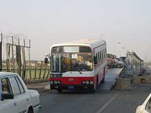
The Mabey Logistic Support Bridge (in the United States, the Mabey-Johnson Bridge) is a portable pre-fabricated truss bridge, designed for use by military engineering units to upgrade routes for heavier traffic, replace civilian bridges damaged by enemy action or floods etc., replace assault and general support bridges and to provide a long span floating bridge capability. The bridge is a variant of the Mabey Compact 200 bridge, with alterations made to suit the military user as well as a ramp system to provide ground clearance to civilian and military vehicles.
Description

The Logistic Support Bridge is a non-assault bridge for the movement of supplies and the re-opening of communications. It is a low-cost system that can be used widely throughout the support area, as well as for a range of defined applications. All types of vehicles including civilian vehicles with low ground clearances are accommodated.
The Mabey Logistic Support Bridge originated from the Bailey bridge concept. Compared with World War II material in use throughout the world, LSB is manufactured with chosen modern steel grades, with a strong steel deck system. With strong deep transoms, there are only two per bay instead of the four previously needed on Bailey bridges.
Beyond the need for the re-opening of communications, Logistic Support Bridge-based equipment (Compact 200) can be used as a rescue bridge for relief in natural disaster situations or as a civilian bridge for semi-permanent bridging to open up communications in some of the most remote regions of the world.
Users


The bridge is manufactured by Mabey Group at its Mabey Bridge factory in Lydney, Gloucestershire (Mabey Group's original factory, now closed, was in Chepstow and manufactured large bridge girders; in May 2019, the Group sold Mabey Bridge to the US-based Acrow Bridge).
The name LSB was given by the British Army (Royal Engineers) to supply bridging to satisfy their specific requirements for a logistic or line of communication bridging. The LSB went into service with the British Army on 21 December 2001. The system is proved and approved by a number of NATO forces.
Armies from a number of countries around the world own equipment or have trained and deployed on the system, notably during the crisis in the Balkans. These armies include Argentina, Austria, Belgium, Brazil, Bulgaria, Cambodia, Canada, Chile, Denmark, Ecuador, Finland, France, Germany, Greece, Hungary, Ireland, Italy, Malaysia, Nepal, Netherlands, Romania, Sri Lanka, Slovakia, Slovenia, Spain, Sweden, Switzerland, Tanzania, Turkey, Venezuela, United Kingdom, United States.
The bridge has been built in many locations across Iraq and Afghanistan by the U.S. Naval Mobile Construction Battalions (Seabees) and the United States Army Corps of Engineers. During the Canadian OPERATION ATHENA, members of 1 CER on Task Force 3-09 constructed a Mabey Logistic Support Bridge over a pre-existing bridge after a vehicle borne suicide bomb detonated on the bridge close to Kandahar Airfield
The Swedish Transport Administration also uses the bridge where it is used during road renovation and construction or as a stop gap after road damage.
Features
- The bridge takes military load class 80 Tracked, 110 Wheeled
- The bridge can span up to 61m
- LSB has a lane width of 4.2m
- Multi-span equipment enables the bridge to be built to any length on fixed or floating supports
- Built on a greenfield site using grillages, ground beams and ramps
- The bridge is normally built using an atc244 22 ton capacity crane or a hydraulic excavator using a bucket with a lifting eye.
System description


The LSB combines standard off the shelf equipment with a range of purpose designed special equipment to meet the expectations of modern military loads and traffic expectations.
- Panels —These are the main structural components of the bridge trusses. They are welded items comprising top and bottom chords interconnected by vertical and diagonal bracing. At the end of each panel, chords terminate in male lugs or eyes and at the other end in female lugs or eyes. This allows panels to be pinned together to form the bridge span. There are two different panels; a Super Panel and a High Shear Super Panel. The High Shear Super Panel is used at each end of the bridge span depending upon the loading criteria.
- Chord reinforcement —These are constructed in the same way as the chords of the bridge panels and are bolted to the panels to increase the bending capacity of the bridge. For the LSB a heavy chord reinforcement is used.
- Transoms —These are fabricated from universal beams and form the cross girders of the bridge, spanning between the panels and carrying the bridge deck. The transom is designed for the appropriate loading criteria and for LSB is designed to accommodate MLC80T/110W.
- Decks —Unlike wooden Bailey decks, the steel LSB decks are 1.05m x 3.05m and are manufactured using robotic welding technology. The decks are manufactured to have a long fatigue life and with durbar/checkered plate finish. The decks withstand both wheeled and tracked vehicles.
- Bracing —A variety of bracing members are used to connect panels to form the bridge trusses and to brace adjacent transoms to the bridge.
- Grillages and Ground Beams —On greenfield sites and when being used as an over bridge, ground beams are available that form an assembly which transmits all dead and live forces from the bridge into the ground. For a 40m (MLC80T/110W) bridge the ground bearing pressure is 200 kN/m2. The grillages are located on the top of the ground beams and accommodate the bridge bearings as well as the head of the ramp transom.
- Ramps —The slope or profile of the ramps can be adjusted to allow for the passage of a range of civilian and military traffic. The length of a standard ramp at each end of the bridge is 13.5m. The ramps are bolted to the grillages and use standard deck units supported on special transoms. These transoms can be positioned at a variety of heights depending upon the set adopted with a special ramp post. The interface between the ramp and ground is a special toe ramp unit (1.5m)
Construction
The bridge can be constructed by the cantilever launch method without the need for any temporary intermediate support. This is achieved by erecting a temporary launching nose at the front of the bridge and pushing the bridge over the gap on rollers.
After pushing the bridge over the gap, the launching nose is dismantled and the bridge is jacked down onto its bearings. The launching nose is largely constructed from standard bridge components.
Floating variants
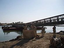
There are a number of floating versions of the Mabey LSB in use across Iraq: Floating Piers which consist of steel Flexifloat pontoon units, Landing Piers consisting of 16 pontoon units, and Intermediate Piers which consist of 8 pontoons each. Hand winches are mounted on steel trays which are bolted to the pontoons. The anchors are connected to the hand winches and pontoons via steel chain and polypropylene ropes. Special span junction decks allow for the rotation of the floating spans as the spans deflect under live load.
If the bridge is relatively short in terms of the number of spans, it may be possible to launch the complete bridge from one bank. On a long span bridge, launching intermediate spans and floating them into position on intermediate piers is more practical.
See also
References
- ^ Mabey & Johnson. "Logistic Support Bridge". M&J UK website. Retrieved 10 December 2009.
- "Acrow buys Mabey Bridge". The Construction Index. 13 May 2019. Retrieved 13 May 2019.
- "Varselgult och grönt samarbete i Örsundsbro".