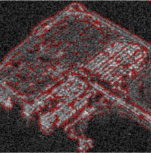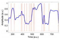


Phase stretch transform (PST) is a computational approach to signal and image processing. One of its utilities is for feature detection and classification. PST is related to time stretch dispersive Fourier transform. It transforms the image by emulating propagation through a diffractive medium with engineered 3D dispersive property (refractive index). The operation relies on symmetry of the dispersion profile and can be understood in terms of dispersive eigenfunctions or stretch modes. PST performs similar functionality as phase-contrast microscopy, but on digital images. PST can be applied to digital images and temporal (time series) data. It is a physics-based feature engineering algorithm.
Operation principle
Here the principle is described in the context of feature enhancement in digital images. The image is first filtered with a spatial kernel followed by application of a nonlinear frequency-dependent phase. The output of the transform is the phase in the spatial domain. The main step is the 2-D phase function which is typically applied in the frequency domain. The amount of phase applied to the image is frequency dependent, with higher amount of phase applied to higher frequency features of the image. Since sharp transitions, such as edges and corners, contain higher frequencies, PST emphasizes the edge information. Features can be further enhanced by applying thresholding and morphological operations. PST is a pure phase operation whereas conventional edge detection algorithms operate on amplitude.
Physical and mathematical foundations of phase stretch transform
Photonic time stretch technique can be understood by considering the propagation of an optical pulse through a dispersive fiber. By disregarding the loss and non-linearity in fiber, the non-linear Schrödinger equation governing the optical pulse propagation in fiber upon integration reduces to:
- (1)
where = GVD parameter, z is propagation distance, is the reshaped output pulse at distance z and time t. The response of this dispersive element in the time-stretch system can be approximated as a phase propagator as presented in (2)
Therefore, Eq. 1 can be written as following for a pulse that propagates through the time-stretch system and is reshaped into a temporal signal with a complex envelope given by
- (3)
The time stretch operation is formulated as generalized phase and amplitude operations,
- (4)
where is the phase filter and is the amplitude filter. Next the operator is converted to discrete domain,
- (5)
where is the discrete frequency, is the phase filter, is the amplitude filter and FFT is fast Fourier transform.
The stretch operator for a digital image is then
- (6)
In the above equations, is the input image, and are the spatial variables, is the two-dimensional fast Fourier transform, and and are spatial frequency variables. The function is the warped phase kernel and the function is a localization kernel implemented in frequency domain. PST operator is defined as the phase of the Warped Stretch Transform output as follows
- (7)
where is the angle operator.
PST kernel implementation
The warped phase kernel can be described by a nonlinear frequency dependent phase
While arbitrary phase kernels can be considered for PST operation, here we study the phase kernels for which the kernel phase derivative is a linear or sublinear function with respect to frequency variables. A simple example for such phase derivative profiles is the inverse tangent function. Consider the phase profile in the polar coordinate system
From we have
Therefore, the PST kernel is implemented as
where and are real-valued numbers related to the strength and warp of the phase profile
Applications
PST has been used for edge detection in biological and biomedical images as well as synthetic-aperture radar (SAR) image processing. PST has also been applied to improve the point spread function for single molecule imaging in order to achieve super-resolution. The transform exhibits intrinsic superior properties compared to conventional edge detectors for feature detection in low contrast visually impaired images.
The PST function can also be performed on 1-D temporal waveforms in the analog domain to reveal transitions and anomalies in real time.
Open source code release
On February 9, 2016, a UCLA Engineering research group has made public the computer code for PST algorithm that helps computers process images at high speeds and "see" them in ways that human eyes cannot. The researchers say the code could eventually be used in face, fingerprint, and iris recognition systems for high-tech security, as well as in self-driving cars' navigation systems or for inspecting industrial products. The Matlab implementation for PST can also be downloaded from Matlab Files Exchange. However, it is provided for research purposes only, and a license must be obtained for any commercial applications. The software is protected under a US patent. The code was then significantly refactored and improved to support GPU acceleration. In May 2022, it became one algorithm in PhyCV: the first physics-inspired computer vision library.
See also
- Edge detection
- Feature detection (computer vision)
- Time stretch analog-to-digital converter
- Time stretch dispersive Fourier transform
- Phase-stretch Adaptive Gradient-field Extractor
- PhyCV
References
- M. H. Asghari, and B. Jalali, "Edge detection in digital images using dispersive phase stretch", International Journal of Biomedical Imaging, Vol. 2015, Article ID 687819, pp. 1–6 (2015).
- M. H. Asghari, and B. Jalali, "Physics-inspired image edge detection", IEEE Global Signal and Information Processing Symposium (GlobalSIP 2014), paper: WdBD-L.1, Atlanta, December 2014.
- Y. Han and B. Jalali, "Photonic time-stretched analog-to-digital converter: fundamental concepts and practical considerations", Journal of Lightwave Technology 21, 3085 (2003)
- ^ B. Jalali and A. Mahjoubfar, "Tailoring Wideband Signals With a Photonic Hardware Accelerator", Proceedings of the IEEE, Vol. 103, No. 7, pp. 1071–1086 (2015).
- Physics-based Feature Engineering. Jalali et al. Optics, Photonics and Laser Technology, 2019
- Agrawal, G. P. (2007). Nonlinear fiber optics. Academic press. Chicago.
- Abdol, A.M.; Bedard, Andrew; Lánský, Imke; Kaandorp, J.A. (2018). "High-throughput method for extracting and visualizing the spatial gene expressions from in situ hybridization images: A case study of the early development of the sea anemone Nematostella vectensis". Gene Expression Patterns. 27: 36–45. doi:10.1016/j.gep.2017.10.005. ISSN 1567-133X. PMID 29122675.
- M. H. Asghari, C. Clemente, B. Jalali, and J. Soraghan, "Synthetic aperture radar image compression using discrete anamorphic stretch transform", IEEE Global Signal and Information Processing Symposium (GlobalSIP 2014), paper: WsBD-P.7, Atlanta, December 2014.
- C. V. Ilioudis, C. Clemente, M. H. Asghari, B. Jalali, and J. Soraghan, "Edge detection in SAR images using Dispersive Phase Stretch Transform", submitted to 2nd IET International Conference on Intelligent Signal Processing, London, 2015
- T. Ilovitsh, B. Jalali, M. H. Asghari, and Z. Zalevsky, "Phase stretch transform for super-resolution localization microscopy", Biomedical optics express. 2016 Oct 1;7(10):4198–209.
- M. Suthar, H. Asghari, and B. Jalali, "Feature Enhancement in Visually Impaired Images", IEEE Access 6 (2018): 1407–1415.
- "JalaliLabUCLA/Image-feature-detection-using-Phase-Stretch-Transform – File Exchange – MATLAB Central".
 (1)
(1) = GVD parameter, z is propagation distance,
  is the reshaped output pulse at distance z and time t. The response of this dispersive element in the time-stretch system can be approximated as a phase propagator as presented in
 (2)
(2)
 (3)
(3) (4)
(4) is the phase filter and
  is the amplitude filter. Next the operator is converted to discrete domain,
 (5)
(5) is the discrete frequency,
  is the phase filter,
  is the amplitude filter and FFT is fast Fourier transform.
 for a digital image is then
 (6)
(6) is the input image,
  and
and  are the spatial variables,
  is the two-dimensional fast Fourier transform, and
  are spatial frequency variables. The function
  is the warped phase kernel and the function
  is a localization kernel implemented in frequency domain. PST operator is defined as the phase of the Warped Stretch Transform output as follows
 (7)
(7) is the angle operator.


 we have

 and
and  are real-valued numbers related to the strength and warp of the phase profile