| Feature detection |
|---|
| Edge detection |
| Corner detection |
| Blob detection |
| Ridge detection |
| Hough transform |
| Structure tensor |
| Affine invariant feature detection |
| Feature description |
| Scale space |


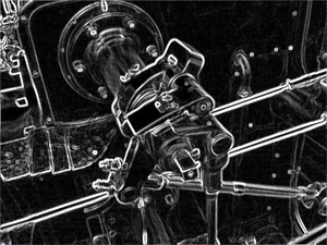
The Sobel operator, sometimes called the Sobel–Feldman operator or Sobel filter, is used in image processing and computer vision, particularly within edge detection algorithms where it creates an image emphasising edges. It is named after Irwin Sobel and Gary M. Feldman, colleagues at the Stanford Artificial Intelligence Laboratory (SAIL). Sobel and Feldman presented the idea of an "Isotropic 3 × 3 Image Gradient Operator" at a talk at SAIL in 1968. Technically, it is a discrete differentiation operator, computing an approximation of the gradient of the image intensity function. At each point in the image, the result of the Sobel–Feldman operator is either the corresponding gradient vector or the norm of this vector. The Sobel–Feldman operator is based on convolving the image with a small, separable, and integer-valued filter in the horizontal and vertical directions and is therefore relatively inexpensive in terms of computations. On the other hand, the gradient approximation that it produces is relatively crude, in particular for high-frequency variations in the image.
Formulation
The operator uses two 3×3 kernels which are convolved with the original image to calculate approximations of the derivatives – one for horizontal changes, and one for vertical. If we define A as the source image, and Gx and Gy are two images which at each point contain the horizontal and vertical derivative approximations respectively, the computations are as follows:
where here denotes the 2-dimensional signal processing convolution operation.
In his text describing the origin of the operator, Sobel shows different signs for these kernels. He defined the operators as neighborhood masks (i.e. correlation kernels), and therefore are mirrored from what described here as convolution kernels. He also assumed the vertical axis increasing upwards instead of downwards as is common in image processing nowadays, and hence the vertical kernel is flipped.
Since the Sobel kernels can be decomposed as the products of an averaging and a differentiation kernel, they compute the gradient with smoothing. For example, and can be written as
The x-coordinate is defined here as increasing in the "right"-direction, and the y-coordinate is defined as increasing in the "down"-direction. At each point in the image, the resulting gradient approximations can be combined to give the gradient magnitude, using:
Using this information, we can also calculate the gradient's direction:
where, for example, is 0 for a vertical edge which is lighter on the right side (for see atan2).
More formally
Since the intensity function of a digital image is only known at discrete points, derivatives of this function cannot be defined unless we assume that there is an underlying differentiable intensity function that has been sampled at the image points. With some additional assumptions, the derivative of the continuous intensity function can be computed as a function on the sampled intensity function, i.e. the digital image. It turns out that the derivatives at any particular point are functions of the intensity values at virtually all image points. However, approximations of these derivative functions can be defined at lesser or larger degrees of accuracy.
The Sobel–Feldman operator represents a rather inaccurate approximation of the image gradient, but is still of sufficient quality to be of practical use in many applications. More precisely, it uses intensity values only in a 3×3 region around each image point to approximate the corresponding image gradient, and it uses only integer values for the coefficients which weight the image intensities to produce the gradient approximation.
Extension to other dimensions
The Sobel–Feldman operator consists of two separable operations:
- Smoothing perpendicular to the derivative direction with a triangle filter:
- Simple central difference in the derivative direction:
Sobel–Feldman filters for image derivatives in different dimensions with :
1D:
2D:
2D:
3D:
3D:
4D:
Thus as an example the 3D Sobel–Feldman kernel in z-direction:
Technical details
As a consequence of its definition, the Sobel operator can be implemented by simple means in both hardware and software: only eight image points around a point are needed to compute the corresponding result and only integer arithmetic is needed to compute the gradient vector approximation. Furthermore, the two discrete filters described above are both separable:
and the two derivatives Gx and Gy can therefore be computed as
In certain implementations, this separable computation may be advantageous since it implies fewer arithmetic computations for each image point.
Applying convolution K to pixel group P can be represented in pseudocode as:
where represents the new pixel matrix resulted after applying the convolution K to P; P being the original pixel matrix.
Example
The result of the Sobel–Feldman operator is a 2-dimensional map of the gradient at each point. It can be processed and viewed as though it is itself an image, with the areas of high gradient (the likely edges) visible as white lines. The following images illustrate this, by showing the computation of the Sobel–Feldman operator on a simple image.
The images below illustrate the change in the direction of the gradient on a grayscale circle. When the sign of and are the same the gradient's angle is positive, and negative when different. In the example below the red and yellow colors on the edge of the circle indicate positive angles, and the blue and cyan colors indicate negative angles. The vertical edges on the left and right sides of the circle have an angle of 0 because there is no local change in . The horizontal edges at the top and bottom sides of the circle have angles of −π/2 and π/2 respectively because there is no local change in . The negative angle for top edge signifies the transition is from a bright to dark region, and the positive angle for the bottom edge signifies a transition from a dark to bright region. All other pixels are marked as black due to no local change in either or , and thus the angle is not defined. Since the angle is a function of the ratio of to pixels with small rates of change can still have a large angle response. As a result noise can have a large angle response which is typically undesired. When using gradient angle information for image processing applications effort should be made to remove image noise to reduce this false response.
 |
 |
Alternative operators
The Sobel–Feldman operator, while reducing artifacts associated with a pure central differences operator, does not exhibit a good rotational symmetry (about 1° of error). Scharr looked into optimizing this property by producing kernels optimized for specific given numeric precision (integer, float…) and dimensionalities (1D, 2D, 3D). Optimized 3D filter kernels up to a size of 5 x 5 x 5 have been presented there, but the most frequently used, with an error of about 0.2° is:
This factors similarly:
Scharr operators result from an optimization minimizing weighted mean squared angular error in the Fourier domain. This optimization is done under the condition that resulting filters are numerically consistent. Therefore they really are derivative kernels rather than merely keeping symmetry constraints. The optimal 8 bit integer valued 3x3 filter stemming from Scharr's theory is
A similar optimization strategy and resulting filters were also presented by Farid and Simoncelli. They also investigate higher-order derivative schemes. In contrast to the work of Scharr, these filters are not enforced to be numerically consistent.
The problem of derivative filter design has been revisited e.g. by Kroon.
Derivative filters based on arbitrary cubic splines were presented by Hast. He showed how first and second order derivatives can be computed correctly using cubic or trigonometric splines by a double filtering approach giving filters of length 7.
Another similar operator that was originally generated from the Sobel operator is the Kayyali operator, a perfect rotational symmetry based convolution filter 3x3.
Orientation-optimal derivative kernels drastically reduce systematic estimation errors in optical flow estimation. Larger schemes with even higher accuracy and optimized filter families for extended optical flow estimation have been presented in subsequent work by Scharr. Second order derivative filter sets have been investigated for transparent motion estimation. It has been observed that the larger the resulting kernels are, the better they approximate derivative-of-Gaussian filters.
Example comparisons
Here, four different gradient operators are used to estimate the magnitude of the gradient of the test image.
 |
 |
 |
 |
 |
See also
- Digital image processing
- Feature detection (computer vision)
- Feature extraction
- Discrete Laplace operator
- Prewitt operator
References
- ^ Irwin Sobel, 2014, History and Definition of the Sobel Operator
- K. Engel (2006). Real-time volume graphics. pp. 112–114.
- Scharr, Hanno, 2000, Dissertation (in German), Optimal Operators in Digital Image Processing .
- B. Jähne, H. Scharr, and S. Körkel. Principles of filter design. In Handbook of Computer Vision and Applications. Academic Press, 1999.
- H. Farid and E. P. Simoncelli, Optimally Rotation-Equivariant Directional Derivative Kernels, Int'l Conf Computer Analysis of Images and Patterns, pp. 207–214, Sep 1997.
- H. Farid and E. P. Simoncelli, Differentiation of discrete multi-dimensional signals, IEEE Trans Image Processing, vol.13(4), pp. 496–508, Apr 2004.
- D. Kroon, 2009, Short Paper University Twente, Numerical Optimization of Kernel-Based Image Derivatives .
- A. Hast., "Simple filter design for first and second order derivatives by a double filtering approach", Pattern Recognition Letters, Vol. 42, no.1 June, pp. 65–71. 2014.
- Dim, Jules R.; Takamura, Tamio (2013-12-11). "Alternative Approach for Satellite Cloud Classification: Edge Gradient Application". Advances in Meteorology. 2013: 1–8. doi:10.1155/2013/584816. ISSN 1687-9309.
- Scharr, Hanno (2007). "Optimal Filters for Extended Optical Flow". Complex Motion. Lecture Notes in Computer Science. Vol. 3417. Berlin, Heidelberg: Springer Berlin Heidelberg. pp. 14–29. doi:10.1007/978-3-540-69866-1_2. ISBN 978-3-540-69864-7.
- Scharr, Hanno, OPTIMAL SECOND ORDER DERIVATIVE FILTER FAMILIES FOR TRANSPARENT MOTION ESTIMATION 15th European Signal Processing Conference (EUSIPCO 2007), Poznan, Poland, September 3–7, 2007.
External links
- Sobel edge detection in OpenCV
- Sobel Filter, in the SciPy Python Library
- Bibliographic citations for Irwin Sobel in DBLP
- Sobel edge detection example using computer algorithms
- Sobel edge detection for image processing

 here denotes the 2-dimensional signal processing
  and
and  can be written as


 is 0 for a vertical edge which is lighter on the right side (for
  see
see 

 :
:


 represents the new pixel matrix resulted after applying the convolution K to P; P being the original pixel matrix.


 and
and  are the same the gradient's angle is positive, and negative when different. In the example below the red and yellow colors on the edge of the circle indicate positive angles, and the blue and cyan colors indicate negative angles. The vertical edges on the left and right sides of the circle have an angle of 0 because there is no local change in

