| Fibre Channel | |
|---|---|
| Layer 4. Protocol mapping | |
| LUN masking | |
| Layer 3. Common services | |
| Layer 2. Network | |
| Fibre Channel fabric Fibre Channel zoning Registered state change notification | |
| Layer 1. Data link | |
| Fibre Channel 8b/10b encoding | |
| Layer 0. Physical |
Switched fabric or switching fabric is a network topology in which network nodes interconnect via one or more network switches (particularly crossbar switches). Because a switched fabric network spreads network traffic across multiple physical links, it yields higher total throughput than broadcast networks, such as the early 10BASE5 version of Ethernet and most wireless networks such as Wi-Fi.
The generation of high-speed serial data interconnects that appeared in 2001–2004 which provided point-to-point connectivity between processor and peripheral devices are sometimes referred to as fabrics; however, they lack features such as a message-passing protocol. For example, HyperTransport, the computer processor interconnect technology, continues to maintain a processor bus focus even after adopting a higher speed physical layer. Similarly, PCI Express is just a serial version of PCI; it adheres to PCI's host/peripheral load/store direct memory access (DMA)-based architecture on top of a serial physical and link layer.
Fibre Channel


In the Fibre Channel Switched Fabric (FC-SW-6) topology, devices are connected to each other through one or more Fibre Channel switches. While this topology has the best scalability of the three FC topologies (the other two are Arbitrated Loop and point-to-point), it is the only one requiring switches, which are costly hardware devices.
Visibility among devices (called nodes) in a fabric is typically controlled with Fibre Channel zoning.
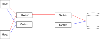
Multiple switches in a fabric usually form a mesh network, with devices being on the "edges" ("leaves") of the mesh. Most Fibre Channel network designs employ two separate fabrics for redundancy. The two fabrics share the edge nodes (devices), but are otherwise unconnected. One of the advantages of such setup is capability of failover, meaning that in case one link breaks or a fabric goes out of order, datagrams can be sent via the second fabric.
The fabric topology allows the connection of up to the theoretical maximum of about 16 million devices, limited only by the available address space (2).
239 domains * 256 areas * 256 ports = 15,663,104
See also
References
- Using Storage Area Networks. Que Publishing. 2002. p. 146. ISBN 978-0-7897-2574-5.
- Hausman, Kirk (2011-03-10). Sustainable Enterprise Architecture. CRC Press. p. 166. ISBN 978-1-4665-0899-6.
- Information Storage and Management: Storing, Managing, and Protecting Digital Information in Classic, Virtualized, and Cloud Environments. John Wiley & Sons. 2012-04-30. p. 109. ISBN 978-1-118-23696-3.
External links
| Network topologies | |
|---|---|
| Arrangements of the data links and nodes of computer networks | |