This is an old revision of this page, as edited by Caden (talk | contribs) at 10:10, 6 February 2010 (Undid revision 342046851 by Fastilysock (talk) Revert vandalism). The present address (URL) is a permanent link to this revision, which may differ significantly from the current revision.
Revision as of 10:10, 6 February 2010 by Caden (talk | contribs) (Undid revision 342046851 by Fastilysock (talk) Revert vandalism)(diff) ← Previous revision | Latest revision (diff) | Newer revision → (diff)| This article does not cite any sources. Please help improve this article by adding citations to reliable sources. Unsourced material may be challenged and removed. Find sources: "Electrical connector" – news · newspapers · books · scholar · JSTOR (March 2008) (Learn how and when to remove this message) |


An electrical connector is a conductive device for joining electrical circuits together. The connection may be temporary, as for portable equipment, or may require a tool for assembly and removal, or may be a permanent electrical joint between two wires or devices. There are hundreds of types of electrical connectors. In computing, an electrical connector can also be known as a physical interface (compare Physical Layer in OSI model of networking). Connectors may join two lengths of flexible wire or cable, or may connect a wire or cable to an electrical terminal.
Properties of electrical connectors
An ideal electrical connector would have a low contact resistance and high insulation value. It would be resistant to vibration, water, oil, and pressure. It would be easily mated/unmated, unambiguously preserve the orientation of connected circuits, reliable, carry one or multiple circuits. Desirable properties for a connector also include easy identification, compact size, rugged construction, durability (capable of many connect/disconnect cycles), rapid assembly, simple tooling, and low cost. No single connector has all the ideal properties. The proliferation of types is a reflection of the differing importance placed on the design factors.
Keying


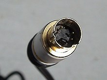
Many connectors are keyed, meaning that they have some component which prevents mating except with specific connectors or in a specific orientation. This can be used to prevent incorrect or damaging interconnections, either preventing pins from being damaged by being jammed in at the wrong angle or fitting into imperfectly fitting plugs, or to prevent damaging connections, such as plugging an audio cable into a power outlet. For instance, XLR connectors have a notch to ensure proper orientation, while Mini-DIN plugs have a plastic projection, which fits into a corresponding hole in the socket and prevent different connectors from being pushed together (they also have a notched metal skirt to provide secondary keying).
Types of electrical connectors
A terminal is a simple type of electrical connector that connects two or more wires to a single connection point. Wire nuts are another type of single point connector.

Terminal blocks
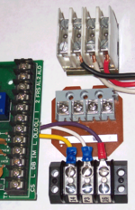
Terminal blocks (also called terminal boards or strips) provide a convenient means of connecting individual electrical wires. They are usually used to connect wiring among various items of equipment within an enclosure or to make connections among individually enclosed items. Since terminal blocks are readily available for a wide range of wire sizes and terminal quantity, they are one of the most flexible types of electrical connector available. Some disadvantages are that connecting wires is more difficult than simply plugging in a cable and the terminals are generally not very well protected from contact with persons or foreign conducting materials.
One type of terminal block accepts wires that are prepared only by removing (stripping) a short length of insulation from the end. Another type accepts wires that have ring or spade terminal lugs crimped onto the wires. Printed circuit board (PCB) mounted terminal blocks allow individual wires to be connected to the circuit board. PCB mounted terminal blocks are soldered to the board, but they are available in a pull-apart version that allows the wire-connecting half of the block to be unplugged from the part that is soldered to the PCB.
Posts

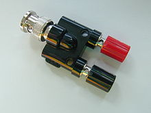
A general type of connector simply screws or clamps bare wire to a post; such connectors are frequently used in electronic test equipment and audio.
Crimp-on terminals
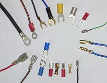
Most types of crimp-on terminals (or lugs) are attached to wires to allow the wires to be easily connected to screw terminals and fast-on or quick-disconnect terminals. There are also crimp-on terminals for connecting two wires together either permanently or with disconnect capability. Crimp-on terminals are attached by inserting the stripped end of a stranded wire into the tubular portion of the terminal. The tubular portion of the terminal is then compressed tightly around the wire or crimped by squeezing it with a special crimping pliers.
Insulation displacement connectors
Main article: Insulation-displacement connectorSince stripping the insulation from wires is time-consuming, many connectors intended for rapid assembly use insulation-displacement connectors so that insulation need not be removed from the wire. These generally take the form of a fork-shaped opening in the terminal, into which the insulated wire is pressed and which cut through the insulation to contact the conductor within. To make these connections reliably on a production line, special tools are used which accurately control the forces applied during assembly. If properly assembled, the resulting terminations are gas-tight and will last the life of the product. A common example is the multi-conductor flat ribbon cable used in computer disk drives; to terminate each of the many (approximately 40) wires individually would be slow and error-prone, but an insulation displacement connector can terminate all the wires in (literally) one stroke. Another very common use is so-called "punch down" blocks used for terminating telephone wiring.
Insulation displacement connectors are usually used with small conductors for signal purposes and at low voltage. Power conductors carrying more than a few amperes are more reliably terminated with other means, though "hot tap" press-on connectors find some use in automotive applications for additions to existing wiring.
Plug and socket connectors
Main article: Gender of connectors and fasteners See also: Pinout
Plug and socket connectors are usually made up of a male plug and a female socket, although hermaphroditic connectors exist, such as the original IBM token ring LAN connector. Plugs generally have one or more pins or prongs that are inserted into openings in the mating socket. The connection between the mating metal parts must be sufficiently tight to make a good electrical connection and complete the circuit. When working with multi-pin connectors, it is helpful to have a pinout diagram to identify the wire or circuit node connected to each pin.


Component and device connectors
Electrical and electronic components and devices sometimes have plug and socket connectors or terminal blocks, but individual screw terminals and fast-on or quick-disconnect terminals are more common. Small components have bare lead wires for soldering. They are manufactured using casting
Blade connector

A blade connector is a type of single wire connection using a flat blade which is inserted into a blade receptacle. Usually both blade connector and blade receptacle have wires attached to them either through soldering of the wire to the blade or crimping of the blade to the wire. In some cases the blade is a manufactured part of a component (such as a switch or a speaker unit) and a blade receptacle is pushed onto the blade to form a connection.
A common type of blade connector is the "faston". Faston connectors come in male and female types. They have been commonly used since 1970s.
Ring and Spade Terminals
The connectors in the top row of the image are known as ring terminals and spade terminals (sometimes called split ring terminals). Electrical contact is made by passing a screw or bolt through them. The spade terminal form factor facilitates connections since the screw or bolt can be left partially screwed in as the spade terminal is removed or attached. Their sizes can be determined by the size of the conducting wire AWG and/or the Screw/Bolt diameter size designation.
Commonly used connectors
8P8C connector

8P8C is short for "eight positions, eight conductors", and so an 8P8C modular connector (plug or jack) is a modular connector with eight positions, all containing conductors. The 8P8C modular plugs and jacks look very similar to the plugs and jacks used for FCC's registered jack RJ45 variants, although the true and extremely uncommon RJ45 is not really compatible with 8P8C modular connectors. It neither uses all eight conductors (but only two of them for wires plus two for shorting a programming resistor) nor does it fit into 8P8C because the true RJ45 is "keyed". The connector is probably most famous for its use in Ethernet and widely used on CAT5 cables.
D-subminiature connectors

The D-subminiature electrical connector is commonly used for the RS-232 serial port on modems and IBM compatible computers. The D-subminiature connector is used in many different applications, for computers, telecommunications, and test and measurement instruments. A few examples are monitors (MGA, CGA, EGA), the Commodore 64, MSX, Apple II, Amiga, and Atari joysticks and mice, and game consoles such as Atari and Sega.
USB connectors
Main article: USB
The Universal Serial Bus is a serial bus standard to interface devices, founded in 1996. It is currently widely used among PCs, Apple Macintosh and many other devices. There are several types of USB connectors, and some have been added as the specification has progressed. The most commonly used is the (male) series "A" plug on peripherals, when the cable is fixed to the peripheral. If there is no cable fixed to the peripheral, the peripheral always needs to have a USB "B" socket. In this case a USB "A" plug to a USB "B" plug cable would be needed. USB "A" sockets are always used on the host PC and the USB "B" sockets on the peripherals. It is a 4-pin connector, surrounded by a shield. There are several other connectors in use, the mini-A, mini- B and mini-AB plug and socket (added in the On-The-Go Supplement to the USB 2.0 Specification).
Power connectors
See Domestic AC power plugs and sockets, NEMA connectors, Industrial and multiphase power plugs and sockets for discussions of connectors used for electric power. Power connectors must protect people from accidental contact with energized conductors. Power connectors often include a safety ground connection as well as the power conductors. In larger sizes, these connectors must also safely contain any arc produced when an energized circuit is disconnected or may require interlocking to prevent opening a live circuit.
Radio frequency connectors
Template:Details3 Connectors used at radio frequencies must not change the impedance of the transmission line of which they are part, otherwise signal reflection and losses will result. A radio-frequency connector must not allow external signals into the circuit, and must prevent leakage of energy out of the circuit. At lower radio frequencies simple connectors can be used with success, but as the radio frequency increases, transmission line effects become more important, with small impedence variations from connectors causing the signal to reflect from the connector, rather than to pass through. At UHF and above, silver-plating of connectors is common to reduce losses.
For Wi-Fi antennas the R-TNC connectors are used. A BNC connector is common for radio and test equipment used up to about 1 GHz.
DC Connectors
A DC connector is an electrical connector for supplying direct current (DC) power
Electrical cables
See also: Electrical cableTermination and gender
Main article: Gender of connectors and fastenersWhen used to terminate cables, in some applications both ends of the cable are terminated using identical connectors (generally male), as in registered jack telephone cables or Ethernet over twisted pair network cables, while in other applications the two ends are terminated differently, either with male and female of the same connector (as in an extension cord), which ends can be connected to each other in a loop, or with incompatible connectors, in an adapter cable.
Wiring
Further information: Pinout See also: Crossover cable
When a cable is terminated by a connector, the various wires in the cable are connected to contacts (pins) in the connector. If one has specified wires within a cable (for instance, the colored Ethernet cable wires in TIA/EIA-568-B), then which color wire connects to which number pin is the wiring. Different ways of wiring the two ends yield different cables which are superficially identical, but behave differently.
If both ends of a cable have the same connector, or male and female versions of a connector, or even similar connectors (such as RJ11 and BS 6312, both of which often have 6P4C (6 positions and 4 contacts)), there is a notion of straight through cable and crossover cable:
- in a straight through cable, pins on one end correspond exactly to the corresponding pins on the other end (pin 1 to pin 1, pin 2 to pin 2, etc.).
- Using the same wiring (a given color wire connects to a given number pin, the same at both ends) at each end yields a straight through cable.
- in a crossover cable, pins do not so correspond; most often in crossover cables some cables are swapped, meaning that if pin 1 on one end goes to pin 2 on the other end, then pin 2 on the first end goes to pin 1 on the second end, and not to pin 3 or some other: such crossover cables are symmetric, meaning that they work identically regardless of which way you plug them in (if you turn the cable around, it still connects the same pins as before).
- Using different wiring (a given color wire connects to one number pin at one end, and a different number pin at the other) at each end yields a crossover cable.
A well-known crossover cable is the Ethernet crossover cable, which converts between T568A and T568B termination.
What matters specifically is not "which contact corresponds to which wire", but rather "which contact on one connector corresponds to which contact on the other connector": to illustrate the distinction, T568A straight through cables and T568B straight through cables are electrically identical: pin 1 on one end corresponds to pin 1 on the other end, though in the T568A it is a green/white striped wire that connects them, while in T568B it is an orange/white striped wire that connects them. However, a cable wired with T568A at one end and T568B at the other is a crossover cable.
The name "straight through" is suggestive but slightly misleading: if one has a ribbon cable, such that all wires are in fact straight and in a line, the pinouts at the two ends are actually the mirror of each other: the left-most wire on one end is the right-most wire on the other.
See also
- Audio and video connector
- Gender of connectors and fasteners
- Wire nut
- Adapter
- Electrical cable
- Electrical termination
- Electrical network
- Physical Layer