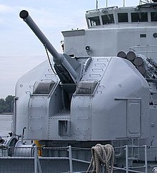
A gun turret (or simply turret) is a mounting platform from which weapons can be fired that affords protection, visibility and ability to turn and aim. A modern gun turret is generally a rotatable weapon mount that houses the crew or mechanism of a projectile-firing weapon and at the same time lets the weapon be aimed and fired in some degree of azimuth and elevation (cone of fire).
Description
Rotating gun turrets protect the weapon and its crew as they rotate. When this meaning of the word "turret" started being used at the beginning of the 1860s, turrets were normally cylindrical. Barbettes were an alternative to turrets; with a barbette the protection was fixed, and the weapon and crew were on a rotating platform inside the barbette. In the 1890s, armoured hoods (also known as "gun houses") were added to barbettes; these rotated with the platform (hence the term "hooded barbette"). By the early 20th century, these hoods were known as turrets. Modern warships have gun-mountings described as turrets, though the "protection" on them is limited to protection from the weather.
Rotating turrets can be mounted on a fortified building or structure such as a coastal blockhouse, be part of a land battery, be mounted on a combat vehicle, a naval ship, or a military aircraft, they may be armed with one or more machine guns, automatic cannons, large-calibre guns, or missile launchers. They may be manned or remotely controlled and are most often protected to some degree, if not actually armoured.
The protection provided by the turret may be against battle damage, the weather conditions, general environment in which the weapon or its crew will be operating. The name derives from the pre-existing noun turret, from the French "touret", diminutive of the word "tower", meaning a self-contained protective position which is situated on top of a fortification or defensive wall as opposed to rising directly from the ground, in which case it constitutes a tower.
Cupolas

A small turret, or sub-turret set on top of a larger one, is called a cupola. The term cupola is also used for a rotating turret that carries a sighting device rather than weaponry, such as that used by a tank commander.
Warships
Before the development of large-calibre, long-range guns in the mid-19th century, the classic battleship design used rows of gunport-mounted guns on each side of the ship, often mounted in casemates. Firepower was provided by a large number of guns, each of which could traverse only in a limited arc. Due to stability issues, fewer large (and thus heavy) guns can be carried high on a ship, but as this set casemates low and thus near the waterline they were vulnerable to flooding, effectively restricted their use to calm seas. Additionally casemate mounts had to be recessed into the side of a vessel to afford a wide arc of fire, and such recesses presented shot traps, compromising the integrity of armour plating.
Rotating turrets were weapon mounts designed to protect the crew and mechanism of the artillery piece and with the capability of being aimed and fired over a broad arc, typically between a three-quarter circle up to a full 360 degrees. These presented the opportunity to concentrate firepower in fewer, better-sited positions by eliminating redundancy, in other words combining the firepower of those guns unable to engage an enemy because they sited on the wrong beam into a more powerful, and more versatile unified battery.
History

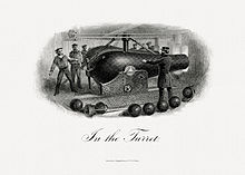
Designs for a rotating gun turret date back to the late 18th century. In the mid-19th century, during the Crimean War, Captain Cowper Phipps Coles constructed a raft with guns protected by a 'cupola' and used the raft, named the Lady Nancy, to shell the Russian town of Taganrog in the Black Sea during the Siege of Taganrog. The Lady Nancy "proved a great success" and Coles patented his rotating turret design after the war.
United Kingdom: Early designs
The British Admiralty ordered a prototype of Coles's patented design in 1859, which was installed in the ironclad floating battery, HMS Trusty, for trials in 1861, becoming the first warship to be fitted with a revolving gun turret. Coles's aim was to create a ship with the greatest possible all round arc of fire, as low in the water as possible to minimise the target.

The Admiralty accepted the principle of the turret gun as a useful innovation, and incorporated it into other new designs. Coles submitted a design for a ship having ten domed turrets each housing two large guns.
The design was rejected as impractical, although the Admiralty remained interested in turret ships and instructed its own designers to create better designs. Coles enlisted the support of Prince Albert, who wrote to the first Lord of the Admiralty, the Duke of Somerset, supporting the construction of a turret ship. In January 1862, the Admiralty agreed to construct a ship, HMS Prince Albert which had four turrets and a low freeboard, intended only for coastal defence.
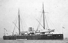
While Coles designed the turrets, the ship was the responsibility of Chief Constructor Isaac Watts. Another ship using Coles' turret designs, HMS Royal Sovereign, was completed in August 1864. Its existing broadside guns were replaced with four turrets on a flat deck and the ship was fitted with 5.5 inches (140 mm) of armour in a belt around the waterline.
Early ships like the Royal Sovereign had little sea-keeping qualities being limited to coastal waters. Sir Edward James Reed, went on to design and build HMS Monarch, the first seagoing warship to carry her guns in turrets. Laid down in 1866 and completed in June 1869, it carried two turrets, although the inclusion of a forecastle and poop prevented the turret guns firing fore and aft.
United States: USS Monitor

The gun turret was independently invented in the United States by the Swedish inventor John Ericsson, although his design was technologically inferior to Coles's version. Ericsson designed USS Monitor in 1861, its most prominent feature being a large, cylindrical gun turret mounted amidships above the low-freeboard upper hull, also referred to as the "raft". This extended well past the sides of the lower, more traditionally shaped hull.
A small, armoured pilot house was fitted on the upper deck towards the bow; however, its position prevented Monitor from firing her guns straight forward. Like Coles's, one of Ericsson's goals in designing the ship was to present the smallest possible target to enemy gunfire. The turret's rounded shape helped to deflect cannon shot. A pair of donkey engines rotated the turret through a set of gears; a full rotation was made in 22.5 seconds during testing on 9 February 1862. However, fine control of the turret proved to be difficult, as it would have to be reversed if it overshot its mark. In lieu of reversing the turret, a full rotation would have to be made to train the guns where desired.

Including the guns, the turret weighed approximately 160 long tons (179 short tons; 163 t); the entire weight rested on an iron spindle that had to be jacked up using a wedge before the turret was free to rotate. The spindle was 9 inches (23 cm) in diameter which gave it ten times the strength needed in preventing the turret from sliding sideways.
When not in use, the turret rested on a brass ring on the deck that was intended to form a watertight seal. However, in service, the interface between the turret and deck ring heavily leaked, despite caulking by the crew.
The gap between the turret and the deck proved to be another kind of problem for several Passaic-class monitors, which used the same turret design, as debris and shell fragments entered the gap and jammed the turrets during the First Battle of Charleston Harbor in April 1863. Direct hits at the turret with heavy shot also had the potential to bend the spindle, which could also jam the turret.
Monitor was originally intended to mount a pair of 15-inch (380 mm) smoothbore Dahlgren guns, but they were not ready in time and 11-inch (280 mm) guns were substituted, each gun weighing approximately 16,000 pounds (7,300 kg). Monitor's guns used the standard propellant charge of 15 pounds (6.8 kg) specified by the 1860 ordnance instructions for targets "distant", "near", and "ordinary", established by the gun's designer Dahlgren himself. They could fire a 136-pound (61.7 kg) round shot or shell up to a range of 3,650 yards (3,340 m) at an elevation of +15°.
Later designs
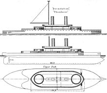
HMS Thunderer (1872) represented the culmination of this pioneering work. An ironclad turret ship designed by Edward James Reed, she was equipped with revolving turrets that used pioneering hydraulic turret machinery to manoeuvre the guns. She was also the world's first mastless battleship, built with a central superstructure layout, and became the prototype for all subsequent warships. With her sister HMS Devastation of 1871 she was another pivotal design, and led directly to the modern battleship.

The US Navy tried to save weight and deck space, and allow the much faster firing 8-inch to shoot during the long reload time necessary for 12-inch guns by superposing secondary gun turrets directly on top of the primary turrets (as in the Kearsarge and Virginia-class battleships), but the idea proved to be practically unworkable and was soon abandoned.
With the advent of the South Carolina-class battleships in 1908, the main battery turrets were designed so as to superfire, to improve fire arcs on centerline mounted weapons. This was necessitated by a need to move all main battery turrets to the vessel's centerline for improved structural support. The 1906 HMS Dreadnought, while revolutionary in many other ways, had retained wing turrets due to concerns about muzzle blast affecting the sighting mechanisms of a turret below. A similar advancement was in the Kongō-class battlecruisers and Queen Elizabeth-class battleships, which dispensed with the "Q" turret amidships in favour of heavier guns in fewer mountings.
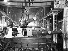
Like pre-dreadnoughts, the first dreadnoughts had two guns in each turret; however, later ships began to be fitted with triple turrets. The first ship to be built with triple turrets was the Italian Dante Alighieri, although the first to be actually commissioned was the Austro-Hungarian SMS Viribus Unitis of the Tegetthoff class. By the beginning of World War II, most battleships used triple or, occasionally, quadruple turrets, which reduced the total number of mountings and improved armour protection. However, quadruple turrets proved to be extremely complex to arrange, making them unwieldy in practice.

The largest warship turrets were in World War II battleships where a heavily armoured enclosure protected the large gun crew during battle. The calibre of the main armament on large battleships was typically 300 to 460 mm (12 to 18 in). The turrets carrying three 460 mm (18 in) guns of Yamato each weighed around 2,500 t (2,500 long tons; 2,800 short tons). The secondary armament of battleships (or the primary armament of light cruisers) was typically between 127 and 152 mm (5.0 and 6.0 in). Smaller ships typically mounted guns of 76 mm (3.0 in) and larger, although these rarely required a turret mounting, except for large destroyers, like the American Fletcher and the German Narvik classes.
Layout

In naval terms, turret traditionally and specifically refers to a gun mounting where the entire mass rotates as one, and has a trunk that projects below the deck. The rotating part of a turret seen above deck is the gunhouse, which protects the mechanism and crew, and is where the guns are loaded. The gunhouse is supported on a bed of rotating rollers, and is not necessarily physically attached to the ship at the base of the rotating structure. In the case of the German battleship Bismarck, the turrets were not vertically restrained and fell out when she sank. The British battlecruiser Hood, like some American battleships, did have vertical restraints.
Below the gunhouse there may be a working chamber, where ammunition is handled, and the main trunk, which accommodates the shell and propellant hoists that bring ammunition up from the magazines below. There may be a combined hoist (cf the animated British turret) or separate hoists (cf the US turret cutaway). The working chamber and trunk rotate with the gunhouse, and sit inside a protective armoured barbette. The barbette extends down to the main armoured deck (red in the animation). At the base of the turret sit handing rooms, where shell and propelling charges are passed from the shell room and magazine to the hoists.
The handling equipment and hoists are complex arrangements of machinery that transport the shells and charges from the magazine into the base of the turret. Bearing in mind that shells can weigh around a 1.6 long tons (1.8 short tons; 1.6 t), the hoists have to be powerful and rapid; a 15 inches (380 mm) turret of the type in the animation was expected to perform a complete loading and firing cycle in a minute.

The loading system is fitted with a series of mechanical interlocks that ensure that there is never an open path from the gunhouse to the magazine down which an explosive flash might pass. Flash-tight doors and scuttles open and close to allow the passage between areas of the turret. Generally, with large-calibre guns, powered or assisted ramming is required to force the heavy shell and charge into the breech.
As the hoist and breech must be aligned for ramming to occur, there is generally a restricted range of elevations at which the guns can be loaded; the guns return to the loading elevation, are loaded, then return to the target elevation, at which time they are said to be "in battery". The animation illustrates a turret where the rammer is fixed to the cradle that carries the guns, allowing loading to occur across a wider range of elevations.
Earlier turrets differed significantly in their operating principles. It was not until the last of the "rotating drum" designs described in the previous section were phased out that the "hooded barbette" arrangement above became the standard.
Wing turrets

A wing turret is a gun turret mounted along the side, or the wings, of a warship, off the centerline.
The positioning of a wing turret limits the gun's arc of fire, so that it generally can contribute to only the broadside weight of fire on one side of the ship. This is the major weakness of wing turrets as broadsides were the most prevalent type of gunnery duels. Depending on the configurations of ships, such as HMS Dreadnought but not SMS Blücher, the wing turrets could fire fore and aft, so this somewhat reduced the danger when an opponent crossed the T enabling it to fire a full broadside.

Attempts were made to mount turrets en echelon so that they could fire on either beam, such as the Invincible-class and SMS Von der Tann battlecruisers, but this tended to cause great damage to the ships' deck from the muzzle blast.
Wing turrets were commonplace on capital ships and cruisers during the late 19th century up until the 1910s. In pre-dreadnought battleships, the wing turret contributed to the secondary battery of sub-calibre weapons. In large armoured cruisers, wing turrets contributed to the main battery, although the casemate mounting was more common. At the time, large numbers of smaller calibre guns contributing to the broadside were thought to be of great value in demolishing a ship's upperworks and secondary armaments, as distances of battle were limited by fire control and weapon performance.

In the early 1900s, weapon performance, armour quality and vessel speeds generally increased along with the distances of engagement; the utility of large secondary batteries reducing as a consequence, and in addition at extreme range it was impossible to see the fall of lesser weapons and so correct the aim. Therefore, most early dreadnought battleships featured "all big gun" armaments of identical calibre, typically 11 or 12 inches (280 or 300 mm), some of which were mounted in wing turrets. This arrangement was not satisfactory, however, as the wing turrets not only had a reduced fire arc for broadsides, but also because the weight of the guns put great strain on the hull and it was increasingly difficult to properly armour them.
Larger and later dreadnought battleships carried superimposed or superfiring turrets (i.e. one turret mounted higher than and firing over those in front of and below it). This allowed all turrets to train on either beam, and increased the weight of fire forward and aft. The superfiring or superimposed arrangement had not been proven until after South Carolina went to sea, and it was initially feared that the weakness of the previous Virginia-class ship's stacked turrets would repeat itself. Larger and later guns (such as the US Navy's ultimate big gun design, the 16"/50 Mark 7|16-inch) also could not be shipped in wing turrets, as the strain on the hull would have been too great.
Modern turrets

Many modern surface warships have mountings for larger calibre guns, although the calibres are now generally between 3 and 5 inches (76 and 127 mm) for use against both air and surface targets. The gunhouses are often just weatherproof covers for the gun mounting equipment and are made of light un-armoured materials such as glass-reinforced plastic. Modern turrets are often automatic in their operation, with no humans working inside them and only a small team passing fixed ammunition into the feed system. Smaller calibre weapons often operate on the autocannon principle, and indeed may not even be turrets at all; they may just be bolted directly to the deck.
Turret identification
On board warships, each turret is given an identification. In the British Royal Navy, these would be letters: "A" and "B" were for the turrets from the front of the ship backwards in front of the bridge, and letters near the end of the alphabet (i.e., "X", "Y", etc.) were for turrets behind the bridge ship, "Y" being the rearmost. Mountings in the middle of the ship would be "P", "Q", "R", etc. Confusingly, the Dido-class cruisers had a "Q" and the Nelson-class battleships had an "X" turret in what would logically be "C" position; the latter being mounted at the main deck level in front of the bridge and behind the "B" turret, thus having restricted training fore and aft.
Secondary turrets were named "P" and "S" (port and starboard) and numbered from fore to aft, e.g. P1 being the forward port turret.
There were exceptions; the battleship HMS Agincourt had the uniquely large number of seven turrets. These were numbered "1" to "7" but were unofficially nicknamed "Sunday", Monday", etc. through to "Saturday".
In German use, turrets were generally named "A", "B", "C", "D", "E", going from bow to stern. Usually the radio alphabet was used on naming the turrets (e.g. "Anton", "Bruno" or "Berta", "Caesar", "Dora") as on the German battleship Bismarck.
In the United States Navy, main battery turrets are numbered fore to aft. Secondary gun mounts are numbered by gun muzzle diameter in inches followed by a second digit indicating the position of the mount, with the second digit increasing fore to aft. Gun mounts not on the centerline would be assigned odd numbers on the port side and even numbers on the starboard side. For example, "Mount 52" would be the forwardmost 5 inches (130 mm) gun mount on the starboard side of the ship.
Aircraft
History
During World War I, air gunners initially operated guns that were mounted on pedestals or swivel mounts known as pintles. The latter evolved into the Scarff ring, a rotating ring mount which allowed the gun to be turned to any direction with the gunner remaining directly behind it, the weapon held in an intermediate elevation by bungee cord, a simple and effective mounting for single weapons such as the Lewis Gun though less handy when twin mounted as with the British Bristol F.2 Fighter and German "CL"-class two-seaters such as the Halberstadt and Hannover-designed series of compact two-seat combat aircraft. In a failed 1916 experiment, a variant of the SPAD S.A two-seat fighter was probably the first aircraft to be fitted with a remotely-controlled gun, which was located in a nose nacelle.
As aircraft flew higher and faster, the need for protection from the elements led to the enclosure or shielding of the gun positions, as in the "lobsterback" rear seat of the Hawker Demon biplane fighter.

The first British operational bomber to carry an enclosed, power-operated turret was the Boulton & Paul Overstrand twin-engined biplane, which first flew in 1933. The Overstrand was similar to its First World War predecessors in that it had open cockpits and hand-operated machine guns. However, unlike its predecessors, the Overstrand could fly at 140 mph (230 km/h) making operating the exposed gun positions difficult, particularly in the aircraft's nose. To overcome this problem, the Overstrand was fitted with an enclosed and powered nose turret, mounting a Lewis gun. Rotation was handled by pneumatic motors while elevation and depression of the gun used hydraulic rams. The pilot's cockpit was also enclosed but the dorsal (upper) and ventral (belly) gun positions remained open, though shielded.

The Martin B-10 all-metal monocoque monoplane bomber introduced turret-mounted defensive armament within the United States Army Air Corps, almost simultaneously with the RAF's Overstrand biplane bomber design. The Martin XB-10 prototype aircraft first featured the nose turret in June 1932—roughly a year before the less advanced Overstrand airframe design—and was first produced as the YB-10 service test version by November 1933. The production B-10B version started service with the USAAC in July 1935.
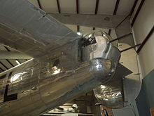
In time the number of turrets carried and the number of guns mounted increased. RAF heavy bombers of World War II such as the Handley Page Halifax (until its Mk II Series I (Special) version omitted the nose turret), Short Stirling and Avro Lancaster typically had three powered turrets: rear, mid-upper and nose. (Early in the war, some British heavy bombers also featured a retractable, remotely-operated ventral/mid-under turret). The rear turret mounted the heaviest armament: four 0.303 in (7.7 mm) Browning machine guns or, late in the war, two AN/M2 light-barrel versions of the US Browning M2 machine gun as in the Rose-Rice turret. The tail gunner or "Tail End Charlie" position was generally accepted to be the most dangerous assignment. During the war, British turrets were largely self-contained units, manufactured by Boulton Paul Aircraft and Nash & Thompson. The same model of turret might be fitted to several different aircraft types. Some models included gun-laying radar that could lead the target and compensate for bullet drop.
As almost a 1930s "updated" adaptation of the First World War Bristol F.2b concept, the UK introduced the concept of the "turret fighter", with aeroplanes such as the Boulton Paul Defiant and Blackburn Roc where the armament was four (0.303 in (7.7 mm)) machine-guns was in a turret mounted behind the pilot, rather than in fixed positions in the wings. The Defiant and Roc possessed no fixed, forward-firing guns; the Bristol F.2 was designed with one synchronized Vickers machine gun firing forward on a fuselage mount.
The concept came at a time when the standard armament of a fighter was only two machine guns and in the face of heavily armed bombers operating in formation, it was thought that a group of turret fighters would be able to concentrate their fire flexibly on the bombers; making beam, stern and rising attacks practicable. Although the idea had some merits in attacking unescorted bombers the weight and drag penalty of the turret (and gunner) put them at a disadvantage when Germany was able to escort its bombers with fighters from bases in Northern France. By this point British fighters were flying with eight machine guns which concentrated firepower for use in single fleeting attacks of fighters against bombers.
Attempts to put this heavier armament, such as multiple 20 mm cannon in low profile aerodynamic turrets were explored by the British in the Boulton Paul P.92 and other designs but were not successful this class of weapons and heavier armament (up to and including artillery pieces as in the 1,420 examples produced of the American B-25G and B-25H Mitchell medium bombers and the experimental 'Tsetse' variant of the de Havilland Mosquito) being exclusively fuselage or underwing-mounted and thus aimed by pointing the aircraft. Not all turret designs put the gunner in the turret along with the armament: US and German-designed aircraft both featured remote-controlled turrets.

In the US, the large, purpose-built Northrop P-61 Black Widow night fighter was produced with a remotely operated dorsal turret that had a wide range of fire though in practice it was generally fired directly forward under control of the pilot. For the last Douglas-built production blocks of the B-17F (the "B-17F-xx-DL" designated blocks) and for all versions of the B-17G Flying Fortress a twin-gun remotely operated "chin" turret, designed by Bendix and first used on the experimental YB-40 "gunship" version of the Fortress, was added to give more forward defence. Specifically designed to be compact and not obstruct the bombardier, this was operated by a swing-away diagonal column possessing a yoke to traverse the turret, and aimed by a reflector sight mounted in the windscreen.

The intended replacement for the German Bf 110 heavy fighter, the Messerschmitt Me 210, possessed twin half-teardrop-shaped, remotely operated Ferngerichtete Drehringseitenlafette (Remote rotating side mount) FDSL 131/1B turrets, one on each side "flank" of the rear fuselage to defend the rear of the aircraft, controlled from the rear area of the cockpit. By 1942, the German He 177A Greif heavy bomber would feature a Fernbedienbare Drehlafette (Remotely controlled rotary carriage) FDL 131Z remotely operated forward dorsal turret, armed with twin 13mm MG 131 machine guns on the top of the fuselage, which was operated from the astrodome a hemispherical, clear rotating observation cover, just behind the cockpit glazing and offset to starboard atop the fuselage—a second, manned powered Hydraulische Drehlafette (Hydraulic rotary mount) HDL 131 dorsal turret, further aft on the fuselage with a MG 131 was also used on most examples.
The US B-29 Superfortress had four remotely controlled turrets, comprising two dorsal and two ventral turrets. These were controlled from a trio of hemispherical, glazed, gunner-manned "astrodome" sighting stations operated from the pressurised sections in the nose and middle of the aircraft, each housing an altazimuth mounted pivoting gunsight to aim one or more of the unmanned remote turrets as needed, in addition to a B-17 style flexible manned tail gunner's station.
The defensive turret on bombers fell from favour with the realization that bombers could not attempt heavily defended targets without escort regardless of their defensive armament unless very high loss rates were acceptable and the performance penalty from the weight and drag of turrets reduced speed, range and payload and increased the number of crew required. The de Havilland Mosquito light bomber was designed to operate without any defensive armament and used its speed to avoid engagement with fighters, much as the minimally armed German Schnellbomber aircraft concepts had been meant to do early in World War II.
A small number of aircraft continued to use turrets, in particular maritime patrol aircraft such as the Avro Shackleton used one as an offensive weapon against small un-armoured surface targets. The Boeing B-52 jet bomber and many of its contemporaries (particularly Russian) featured a barbette (a British English term equivalent to the American usage of the term 'tail gun'), or a "remote turret"—an unmanned turret but often one with a more limited field of fire than a manned equivalent.
Layout
Aircraft carry their turrets in various locations:
- "dorsal" – on top of the fuselage, sometimes referred to as a mid-upper turret.
- "ventral" – underneath the fuselage, often on US heavy bombers, a Sperry-designed ball turret.
- "rear" or "tail" – at the very end of the fuselage.
- "nose" – at the front of the fuselage.
- "cheek" – on the flanks of the nose, as single-gun flexible defensive mounts for B-17 and B-24 heavy bombers
- "chin" – below the nose of the aircraft as on later versions of the Boeing B-17 Flying Fortress.
- "wing" – a handful of very large aircraft, such as the Messerschmitt Me 323 and the Blohm & Voss BV 222, had manned turrets in the wings
- "waist" or "beam" – mounted on the sides of the rear fuselage e.g. US twin- and four-engined bombers.
Gallery
-
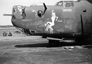 Consolidated B-24J Liberator nose turret
-
 Dorsal gun turret on a Grumman TBM Avenger
-
 B-29 remote controlled aft ventral turret
-
 Wing turrets of an Me 323
-
 Avro Lancaster tail turret
-
 The tail turret or "barbette" of a Boeing B-52 Stratofortress
Combat vehicles
History
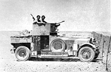
Amongst the first armoured vehicles to be equipped with a gun turret were the Lanchester and Rolls-Royce Armoured Cars, both produced from 1914. The Royal Naval Air Service (RNAS) raised the first British armoured car squadron during the First World War. In September 1914 all available Rolls-Royce Silver Ghost chassis were requisitioned to form the basis for the new armoured car. The following month a special committee of the Admiralty Air Department, among whom was Flight Commander T.G. Hetherington, designed the superstructure which consisted of armoured bodywork and a single fully rotating turret holding a regular water cooled Vickers machine gun.
However, the first tracked combat vehicles were not equipped with turrets due to the problems with getting sufficient trench crossing while keeping the centre of gravity low, and it was not until late in World War I that the French Renault FT light tank introduced the single fully rotating turret carrying the vehicle's main armament that continues to be the standard of almost every modern main battle tank and many post-World War II self-propelled guns. The first turret designed for the FT was a circular, cast steel version almost identical to that of the prototype. It was designed to carry a Hotchkiss 8 mm (0.315 in) machine gun. Meanwhile, the Berliet Company produced a new design, a polygonal turret of riveted plate, which was simpler to produce than the early cast steel turret. It was given the name "omnibus", since it could easily be adapted to mount either the Hotchkiss machine gun or the Puteaux 37 mm (1.5 in) with its telescopic sight. This turret was fitted to production models in large numbers.
In the 1930s, several nations produced multi-turreted tanks—probably influenced by the experimental British Vickers A1E1 Independent of 1926. Those that saw combat during the early part of World War II performed poorly and the concept was soon dropped. Combat vehicles without turrets, with the main armament mounted in the hull, or more often in a completely enclosed, integral armored casemate as part of the main hull, saw extensive use by both the German (as Sturmgeschütz and Jagdpanzer vehicles) and Soviet (as Samokhodnaya Ustanovka vehicles) armored forces during World War II as tank destroyers and assault guns. However, post-war, the concept fell out of favour due to its limitations, with the Swedish Stridsvagn 103 'S-Tank' and the German Kanonenjagdpanzer being exceptions.
Layout

In modern tanks, the turret is armoured for crew protection and rotates a full 360 degrees carrying a single large-calibre tank gun, typically in the range of 105 and 125 mm (4.1 and 4.9 in) calibre. Machine guns may be mounted inside the turret, which on modern tanks is often on a "coaxial" mount, parallel with the larger main gun.
Early designs often featured multiple weapons mounts. This concept was carried forwards into the early interwar years in Britain, Germany and the Soviet Union, arguably reaching its most absurd expression in the British Vickers A1E1 Independent tank, though this attempt was soon abandoned while the Soviet Union's similar effort produced a 'land battleship' which was actually produced and fought in defence of the Soviet Union.
In modern tanks, the turret houses all the crew except the driver (who is located in the hull). The crew located in the turret typically consist of tank commander, gunner, and often a gun loader (except in tanks that have an autoloader), while the driver sits in a separate compartment with a dedicated entry and exit, though often one that allows the driver to exit via the turret basket (fighting compartment).
For other combat vehicles, the turrets are equipped with other weapons dependent on role. An infantry fighting vehicle may carry a smaller calibre gun or an autocannon, or an anti-tank missile launcher, or a combination of weapons. A modern self-propelled gun mounts a large artillery gun but less armour. Lighter vehicles may carry a one-man turret with a single machine gun, occasionally the same model being shared with other classes of vehicle, such as the Cadillac Gage T50 turret/weapons station.
The size of the turret is a factor in combat vehicle design. One dimension mentioned in terms of turret design is "turret ring diameter" which is the size of the aperture in the top of the chassis into which the turret is seated.
Land fortifications
In 1859, the Royal Commission on the Defence of the United Kingdom were in the process of recommending a huge programme of fortifications to protect Britain's naval bases. They interviewed Captain Coles, who had bombarded Russian fortifications during the Crimean War, however Coles repeatedly lost his temper during the discussion and the commissioners failed to ask him about the gun turret that he had patented earlier in that year, with the result that none of the Palmerston Forts mounted turrets. Eventually, the Admiralty Pier Turret at Dover was commissioned in 1877 and completed in 1882.
In continental Europe, the invention of high explosive shells in 1885 threatened to make all existing fortifications obsolete; a partial solution was the protection of fortress guns in armoured turrets. Pioneering designs were produced by Commandant Henri-Louis-Philippe Mougin in France and Captain Maximilian Schumann in Germany. Mougin's designs were incorporated in a new generation of polygonal forts constructed by Raymond Adolphe Séré de Rivières in France and Henri Alexis Brialmont in Belgium. Developed versions of Schumann's turrets were employed after his death in the fortifications of Metz. In 1914, the Brialmont forts in the Battle of Liège proved unequal to the German "Big Bertha" 42 cm siege howitzers, which were able to penetrate the turret armour and smash turret mountings.

Elsewhere, armoured turrets, sometimes described a cupolas, were incorporated into coastal artillery defences. An extreme example was Fort Drum, the "concrete battleship", near Corregidor, Philippines; this mounted four huge 14-inch guns in two naval pattern turrets and was the only permanent turreted fort ever constructed by the United States. Between the wars, improved turrets formed the offensive armament of the Maginot Line forts in France. During the Second World War, some of the artillery pieces in the Atlantic Wall fortifications, such as the Cross-Channel guns, were large naval guns housed in turrets.
Some nations, from Albania to Switzerland and Austria, have embedded the turrets of obsolete tanks in concrete bunkers, while others have constructed or updated fortifications with modern artillery systems, such as the 1970s era Swedish coastal artillery battery on Landsort Island.
Gallery
-
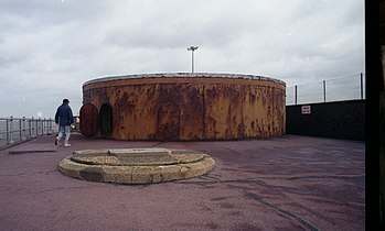 The Admiralty Pier Turret was built to protect the port of Dover in 1882.
-
 A German built 190 mm gun turret at Fort Copacabana in Brazil, completed in 1914.
-
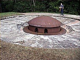 Turret of the Maginot Line; this could retract into the ground when not firing, for added protection.
-
A twin 305 mm gun turret at Kuivasaari, Finland, completed in 1935.
-
 One of three 40.6cm guns at Batterie "Lindemann", a German Cross-Channel gun.
-
12 cm tornautomatpjäs m/70 developed to defend vital points like seaports from enemy landing ships, as well as area denial and fire support, even on a nuclear battlefield.
See also
- Barbette
- Casemate
- Director (military)
- Gun carriage
- Gun mount
- Gun shield
- Rangefinder
- Remote weapon system
- Sponson
Footnotes
- ^ In architecture, a cupola is a small, most often dome-like, structure on top of a building, so although it is often used to describe a sub-turret such as commander's sub-turret on a tank turret, if a gun turret is mounted on a vessel or above a bunker and is dome shaped it too may be referred to as a cupola in some sources.
- See box battery and central battery ship
- Ericsson later admitted that this was a serious flaw in the ship's design and that the pilot house should have been placed atop the turret.
- Something similar occurred in American armoured vehicle designs around the time of the Second World War, tanks sprouting 'superfiring' turrets including the M3 Lee and M60A2 Patton. Given they were generally intended for an already-overburdened commander to operate, they have largely been abandoned in favour of literally lower-profile arrangements for protected observation with, in some cases, top-mounted remotely-operated weapons.
- The Nelson design was an adaption of an earlier planned battleship with two turrets before the bridge and a single one behind the bridge but in front of the aft superstructure.
References
- "Turret n." Online Etymology Dictionary. Retrieved 21 February 2019.
- Davis, William C. (2012). Duel Between the First Ironclads. Knopf Doubleday Publishing Group. ISBN 9780307817501. Retrieved 29 May 2017 – via Google Books.
- Preston, Antony (2002). The World's Worst Warships. London: Conway Maritime Press. p. 21. ISBN 978-0-85177-754-2.
- ^ Barnaby, K. C. (1968). Some ship disasters and their causes. London: Hutchinson. pp. 20–30.
- Barnaby, K.C. (1968). Some ship disasters and their causes. London: Hutchinson. pp. 28–29.
- Sandler, Stanley (2004). Battleships: An Illustrated History of Their Impact. ABC-CLIO. pp. 27–33. ISBN 9781851094103.
- Tucker, Spencer (2006). Blue & gray navies: the Civil War afloat. Maryland: Naval Institute Press. p. 171. ISBN 978-1-59114-882-1.
- ^ Thompson, Stephen C. (1990). "The Design and Construction of the USS Monitor". Warship International. XXVII (3). Toledo, Ohio: International Naval Research Organization. ISSN 0043-0374.
- Mindell, David A. (2000). War, Technology, and Experience Aboard the USS Monitor. Johns Hopkins University Press. p. 41. ISBN 978-0-8018-6250-2.
- McCordock, Robert Stanley (1938). The Yankee Cheese Box. Dorrance. p. 31.
- Baxter, James Phinney, 3rd (1968). The Introduction of the Ironclad Warship (1933 reprintpublication ed.). Hamden, Connecticut: Archon Books. p. 256. OCLC 695838727.
{{cite book}}: CS1 maint: multiple names: authors list (link) CS1 maint: numeric names: authors list (link) - Canney, Donald L. (1993). The Old Steam Navy. Vol. 2: The Ironclads, 1842–1885. Annapolis, Maryland: Naval Institute Press. pp. 79–80. ISBN 978-0-87021-586-5.
- Reed, Sir Edward James (1869). Our Iron-clad Ships: Their Qualities, Performances, and Cost. With Chapters on Turret Ships, Iron-clad Rams. London: J. Murray. pp. 253–254.
- Broadwater, John D. (2012). USS Monitor: A Historic Ship Completes Its Final Voyage. Texas A&M University Press. p. 8. ISBN 978-1-60344-473-6.
- Wilson, H. W. (1896). Ironclads in Action: A Sketch of Naval Warfare From 1855 to 1895. Vol. 1. Boston: Little, Brown. p. 30.
- Field, Ron (2011). Confederate Ironclad vs Union Ironclad: Hampton Roads. Osprey Publishing. p. 33. ISBN 978-1-78096-141-5.
- Olmstead, Edwin; Stark, Wayne E.; Tucker, Spencer C. (1997). The Big Guns: Civil War Siege, Seacoast, and Naval Cannon. Alexandria Bay, New York: Museum Restoration Service. p. 90. ISBN 978-0-88855-012-5.
- Lyon, David & Winfield, Rif (2004). The Sail and Steam Navy List, all the ships of the Royal Navy 1815-1889. Chatham. ISBN 1-86176-032-9 pp. 240–42.
- Jurens, William; Garzke, William H. Jr.; Dulin, Robert O. Jr.; Roberts, John; Fiske, Richard, A Marine Forensic Analysis of HMS Hood and DKM Bismarck, p. 14, CiteSeerX 10.1.1.202.317
- "Armaments & Innovations - The Navy's 'Supershells'". U.S. Naval Institute. 2015-02-09. Retrieved 2024-12-20.
- Roskill, S. W. (1997). Warspite, Classics of Naval Literature, Naval Institute Press. ISBN 1-55750-719-8
- Keegan, John (1989). The Price of Admiralty. New York: Viking. p. 281. ISBN 978-0-670-81416-9.
- Reuter, Claus (2000). Development of Aircraft Turrets in the AAF, 1917–1944, Scarborough, Ont., German Canadian Museum of Applied History, p. 11.
- "The Overstrand's Turret". Flight, 1936.
- "Graphic of usage and stowage positions for B-17G chin turret control yoke". www.lonesentry.com.
- Willmott, H. P. (2003). First World War. Dorling Kindersley, p. 59.
- Crick, Timothy (2012). Ramparts of Empire: The Fortifications of Sir William Jervois, Royal Engineer 1821–1897, University of Exeter Press, ISBN 978-1-905816-04-0, pp. 46–47.
- Donnell, Clayton. Breaking the Fortress Line 1914, pp. 8–13. Pen & Sword Military, ISBN 978-1848848139.
- Hogg, Ian V. (1975). Fortress: A History of Military Defence, pp. 118–19. Macdonald and Jane's. ISBN 0-356-08122-2.
- Hogg. p. 116
Bibliography
- Brown, J. (1977). "RCT Armament in the Boeing B-29". Air Enthusiast. No. 3. pp. 80–83. ISSN 0143-5450.
External links
 Media related to Gun turrets at Wikimedia Commons
- Air Gunnery Archived 2014-01-11 at the Wayback Machine November 1943 Popular Science article on aircraft turrets
- Flight article on aircraft gun turrets amongst others
- Lone Sentry's Bendix B-17 chin turret manual and details