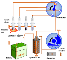

A distributor is an electric and mechanical device used in the ignition system of older spark ignition engines. The distributor's main function is to route electricity from the ignition coil to each spark plug at the correct time.
Design
| This section needs additional citations for verification. Please help improve this article by adding citations to reliable sources in this section. Unsourced material may be challenged and removed. Find sources: "Distributor" – news · newspapers · books · scholar · JSTOR (January 2023) (Learn how and when to remove this message) |
A distributor consists of a rotating arm ('rotor') that is attached to the top of a rotating 'distributor shaft'. The rotor constantly receives high-voltage electricity from an ignition coil via brushes at the centre of the rotor. As the rotor spins, its tip passes close to (but does not touch) the output contacts for each cylinder. As the electrified tip passes each output contact, the high-voltage electricity is able to 'jump' across the small gap. This burst of electricity then travels to the spark plug (via high tension leads), where it ignites the air-fuel mixture in the combustion chamber.
On most overhead valve engines, the distributor shaft is driven by a gear on the camshaft, often shared with the oil pump; on most overhead camshaft engines, the distributor shaft is attached directly to a camshaft.
Older distributor designs used a cam on the distributor shaft that operates the contact breaker (also called points). Opening the points causes a high induction voltage in the ignition coil. This design was superseded by an electronically controlled ignition coil with a sensor (usually Hall effect or optical) to control the timing of the ignition coil charging.
Ignition advance
In older distributors, adjusting the ignition timing is usually achieved through both mechanical advance and vacuum advance. Mechanical advance adjusts the timing based on the engine speed (rpm), using a set of hinged weights attached to the distributor shaft. These weights cause the breaker points mounting plate to slightly rotate, thereby advancing the ignition timing. Vacuum advance typically uses manifold vacuum to adjust the ignition timing, for example to improve fuel economy and driveability when minimal power is required from the engine.
Most distributors used on electronic fuel injection engines use electronics to adjust the ignition timing, instead of vacuum and centrifugal systems. This allows the ignition timing to be optimised based on factors other than engine speed and manifold vacuum.
Direct ignition
Since the early 2000s, many cars have used a 'coil-on-plug' direct ignition system, whereby a small ignition coil is located directly above the spark plug for each cylinder. This design means that high-voltage electricity is only present in the small distance between each coil and the spark plug. See Saab Direct Ignition.
Gallery
-
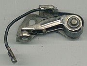
 Breaker arm with contact points at the left. The pivot is on the right and the cam follower is in the middle of the breaker arm.
-
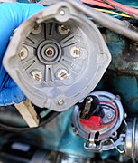
 Distributor cap. At the center is a spring-loaded carbon button that touches the rotor. The number of contacts (in this case 4) is the same as the number of engine cylinders.
-
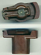
 Rotor. This rotates at the same speed as the camshaft, one half the speed of the crankshaft.
-
 Top of distributor with wires and terminals
-
 Rotor contacts inside distributor cap
History
The first mass-produced electric ignition was the Delco ignition system, which was introduced in the 1910 Cadillac Model 30. In 1921, Arthur Atwater Kent Sr invented the competing Unisparker ignition system.
By the 1980s and 1990s, distributors had been largely replaced by electronic ignition systems.
See also
References
- ^ "How the ignition system works". How a Car Works. Retrieved 2016-02-12.
- "Cadillac History | Kanter Car Tales". kanter-car-tales.com. Archived from the original on 2016-03-05. Retrieved 2016-02-12.
| Internal combustion engine | |
|---|---|
| Part of the Automobile series | |
| Engine block and rotating assembly | |
| Valvetrain and Cylinder head | |
| Forced induction | |
| Fuel system | |
| Ignition | |
| Engine management | |
| Electrical system | |
| Intake system | |
| Exhaust system | |
| Cooling system | |
| Lubrication | |
| Other | |