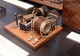
 Closeup of foxhole radio, showing detector made of razor blade with pencil lead attached to safety pin pressing against it
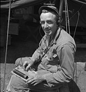
 Soldier at the Anzio beachhead using foxhole radio
A foxhole radio is a makeshift radio that was built by soldiers in World War II for entertainment, to listen to local radio stations using amplitude modulation. They were first reported at the Battle of Anzio, Italy, spreading later across the European and Pacific theaters. The foxhole radio was a crude crystal radio which used a safety razor blade as a radio wave detector with the blade acting as the crystal, and a wire, safety pin, or, later, a graphite pencil lead serving as the cat's whisker.
The foxhole radio, like a mineral crystal radio receiver, had no power source and ran off the power received from the radio station. They were named, likely by the press, for the foxhole, a defensive fighting position used during the war. There are also accounts of prisoners of war in World War II and in the Vietnam War having constructed foxhole radios.
History
The maker of the first foxhole radio is unknown, but it was almost certainly invented by a soldier stationed at the Anzio beachhead during the stalemate of February – May 1944. One of the first newspaper articles about a foxhole radio ran in the New York Times on April 29, 1944. That radio was built by Private Eldon Phelps of Enid, Oklahoma, who later claimed to have invented the design. It was fairly crude, a razor blade stuck into a piece of wood acted as the crystal, and the end of the antenna wire served as a cat whisker. He managed to pick up broadcasts from Rome and Naples.
The idea spread across the beachhead and beyond. Toivo Kujanpaa built a receiver at Anzio and was able to receive German propaganda programs. The propaganda programs were directed towards Allied military from an Axis station in Rome. Many veterans of Anzio refer to the female announcer they heard as "Axis Sally", the nickname usually used when referring to propagandist Mildred Gillars, however Gillars broadcast from Berlin, and the men at Anzio were more likely hearing Rita Zucca, who broadcast from Rome. Though Gillars is more often associated with the "Sally" moniker, it was Zucca who actually referred to herself as "Sally" during broadcasts.
There were also allied broadcasts available, from the 5th Army Mobile Radio Station and the BBC.
American G.I.s in Italy would put several radios together. The G.I.s would listen at night near the front lines to phonograph records played on a radio station in Rome. One could typically hear a radio station on a foxhole radio if they lived twenty five or thirty miles away. In 1942, Lieutenant Colonel R. G. Wells—a prisoner of war in Japan—built a foxhole radio to get news about the international situation. "The whole POW camp craved news", according to Wells. Richard Lucas, a POW in Vietnam, constructed a radio in camp and built his own earphones.
Designs and operation

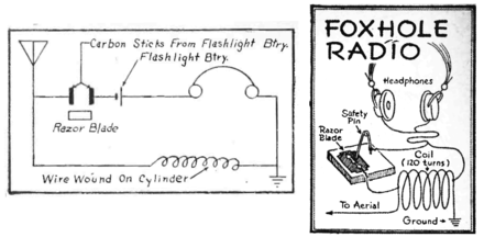
Foxhole radios consisted of a wire aerial, a coil of wire serving as inductor, headphones, and some sort of improvised diode detector to rectify the signal. Detectors consisted of an electrical contact between two different conductors with a semiconducting film of corrosion between them. They were devised from various common objects. One common type was made from an oxidized razor blade (rusty or flamed) with a pencil lead pressed against the blade with a safety pin. The oxide layer on the blade and the point contact of the pencil lead form a semiconductor Schottky diode and only allow current to pass in one direction. Only certain sites on the blade acted as diodes, so the soldier moved the pencil lead around on the surface until the radio station was heard in the earphones. Another detector design was a battery carbon resting across the edges of two vertical razor blades, based on the 1879 "microphone" detector of David Edward Hughes.
The aerial is connected to the grounded inductor. The coil has an internal parasitic capacitance which, along with the capacitance of the antenna forms a resonant circuit (tuned circuit) with the inductance of the coil, resonating at a specific resonant frequency. The coil has a high impedance at its resonant frequency, and passes radio signals from the antenna at that frequency along to the detector, while conducting signals at all other frequencies to ground. By varying the inductance with a sliding contact arm, a commercial crystal radio can be tuned to receive different frequencies. Most of these wartime sets did not have a sliding contact and were only built to receive one frequency, the frequency of the nearest broadcast station. The detector and earphones were connected in series across the coil, which applied the radio signal of the received radio station. The detector acted as a rectifier, allowing current to flow through it in only one direction. It rectified the oscillating radio carrier wave, extracting the audio modulation, which passed through the earphones. The earphones converted the audio signal to sound waves.
Usually the earphones had to be scrounged or borrowed from the unit's communication officer. In one case a soldier, Richard Lucas, built earphones by binding four nails together with cloth then winding wire and dripping wax over the turns. After about ten layers of wire he placed it in a piece of bamboo. A tin can lid was placed over the coil of wire. The listener connected the improvised earphone to the foxhole radio and received three radio stations. The best listening was at night, according to Lucas.
See also
References
- ^ Germs back, Hugo (September 1944). "Foxhole Emergency Radios" (PDF). Radio Craft. 15 (12). Radcraft Publications: 730. Retrieved 29 July 2020.
- ^ Carusella, Brian (2019). Foxhole Radio: the ubiquitous razor blade radio of WWII. Canyon Wren Press. pp. 179–182. ISBN 978-0578536583.
- ^ Gould, Jack (1953). All About Radio and Television. Random House. pp. 58–72.
- "G.I. Uses Razor as Radio". New York Times. 29 April 1944.
- Make a crystal radio, wikihow.com, retrieved 2011-10-21
- R G Wells: The need for a radio., Oral History Research Unit at Bournemouth University, retrieved 2011-10-19
- This detector was described in 1909 in an amateur radio magazine Pettingill, Clark (January 1909). "Novel Detector" (PDF). Modern Electrics. 10 (1). Modern Electrics Publication: 352.


