In mechanical engineering, a helix angle is the angle between any helix and an axial line on its right, circular cylinder or cone. Common applications are screws, helical gears, and worm gears.
The helix angle references the axis of the cylinder, distinguishing it from the lead angle, which references a line perpendicular to the axis. Naturally, the helix angle is the geometric complement of the lead angle. The helix angle is measured in degrees.
Concept
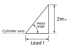
In terms specific to screws, the helix angle can be found by unraveling the helix from the screw, representing the section as a right triangle, and calculating the angle that is formed. Note that while the terminology directly refers to screws, these concepts are analogous to most mechanical applications of the helix angle.
The helix angle can be expressed as:
where
- l is lead of the screw or gear
- rm is mean radius of the screw thread or gear
Applications
The helix angle is crucial in mechanical engineering applications that involve power transfer and motion conversion. Some examples are outlined below, though its use is much more widely spread.
Screw

Cutting a single helical groove into a screw-stock cylinder yields what is referred to as a single-thread screw. Similarly, one may construct a double-thread screw provided that the helix angle of the two cuts is the same, and that the second cut is positioned in the uncut material between the grooves of the first. For certain applications, triple and quadruple threads are in use. The helix may be cut either right hand or left hand. In screws especially, the helix angle is essential for calculating torque in power screw applications.
The maximum efficiency for a screw is defined by the following equations:
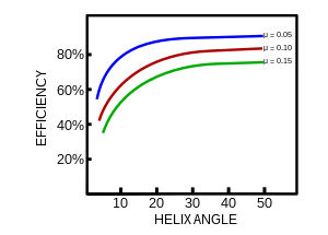
Where is the helix angle, is the friction angle, and is the maximum efficiency. The friction value is dependent on the materials of the screw and interacting nut, but ultimately the efficiency is controlled by the helix angle. The efficiency can be plotted versus the helix angle for a constant friction, as shown in the adjacent diagram. The maximum efficiency is a helix angle between 40 and 45 degrees, however a reasonable efficiency is achieved above 15°. Due to difficulties in forming the thread, helix angle greater than 30° are rarely used. Moreover, above 30° the friction angle becomes smaller than the helix angle and the nut is no longer self-locking and the mechanical advantage disappears.
Helical gear

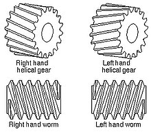
In helical and worm gears, the helix angle denotes the standard pitch circle unless otherwise specified. Application of the helix angle typically employs a magnitude ranging from 15° to 30° for helical gears, with 45° capping the safe operation limit. The angle itself may be cut with either a right-hand or left-hand orientation. In its typical parallel arrangement, meshing helical gears requires that the helix angles are of the same magnitude and cut oppositely .
Worm gear
Worm gears resemble helical gear seats, the difference being that the shafts of a worm train are aligned perpendicularly. In this case, the helix angle of the worm meshes with the lead angle of the worm gear.
See also
References
- ^ Gear Nomenclature, Definition of Terms with Symbols, American Gear Manufacturers Association, p. 72, ISBN 1-55589-846-7, OCLC 65562739, ANSI/AGMA 1012-G05
- Shigley, p. 401.
- Norton, Robert L., Machine Design: An Integrated Approach. 3rd ed. Upper Saddle River, NJ: Pearson Prentice Hall, 2006.
- ^ Karwa, p. 252.
- Shigley, Joseph E., and Larry D. Mitchell Mechanical Engineering Design. 4th ed. New York: McGraw-Hill, Inc, 1983.
- Spotts, M F., and T E. Shoup. Design of Machine Elements. 7th ed. Upper Saddle River, NJ: Prentice Hall, 1998.
Bibliography
- Bhandari, V B (2007), Design of Machine Elements, Tata McGraw-Hill, ISBN 978-0-07-061141-2.
- Karwa, Rajendra (2005), A textbook of machine design, Firewall Media, ISBN 978-81-7008-833-2.
| Spirals, curves and helices | |||
|---|---|---|---|
| Curves |  | ||
| Helices |
| ||
| Spirals | |||


 is the helix angle,
  is the
  is the maximum efficiency. The friction value is dependent on the materials of the screw and interacting nut, but ultimately the efficiency is controlled by the helix angle. The efficiency can be plotted versus the helix angle for a constant friction, as shown in the adjacent diagram. The maximum efficiency is a helix angle between 40 and 45 degrees, however a reasonable efficiency is achieved above 15°. Due to difficulties in forming the thread, helix angle greater than 30° are rarely used. Moreover, above 30° the friction angle becomes smaller than the helix angle and the nut is no longer self-locking and the mechanical advantage disappears.