| This article needs additional citations for verification. Please help improve this article by adding citations to reliable sources. Unsourced material may be challenged and removed. Find sources: "Hypersonic wind tunnel" – news · newspapers · books · scholar · JSTOR (November 2021) (Learn how and when to remove this message) |

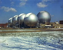
A hypersonic wind tunnel is designed to generate a hypersonic flow field in the working section, thus simulating the typical flow features of this flow regime - including compression shocks and pronounced boundary layer effects, entropy layer and viscous interaction zones and most importantly high total temperatures of the flow. The speed of these tunnels vary from Mach 5 to 15. The power requirement of a wind tunnel increases linearly with its cross section and flow density, but cubically with the test velocity required. Hence installation of a continuous, closed circuit wind tunnel remains a costly affair. The first continuous Mach 7-10 wind tunnel with 1x1 m test section was planned at Kochel am See, Germany during WW II and finally put into operation as 'Tunnel A' in the late 1950s at AEDC Tullahoma, TN, USA for an installed power of 57 MW. In view of these high facility demands, also intermittently operated experimental facilities like blow-down wind tunnels are designed and installed to simulate the hypersonic flow. A hypersonic wind tunnel comprises in flow direction the main components: heater/cooler arrangements, dryer, convergent/divergent nozzle, test section, second throat and diffuser. A blow-down wind tunnel has a low vacuum reservoir at the back end, while a continuously operated, closed circuit wind tunnel has a high power compressor installation instead. Since the temperature drops with the expanding flow, the air inside the test section has the chance of becoming liquefied. For that reason, preheating is particularly critical (the nozzle may require cooling).
Technological problems
There are several technological problems in designing and constructing a hyper-velocity wind tunnel:
- supply of high temperatures and pressures for times long enough to perform a measurement
- reproduction of equilibrium conditions
- structural damage produced by overheating
- fast instrumentation
- power requirements to run the tunnel
Simulations of a flow at 5.5 km/s, 45 km altitude would require tunnel temperatures of as much as 9000 K, and a pressure of 3 GPa.
Hot shot wind tunnel
One form of HWT is known as a Gun Tunnel or hot shot tunnel (up to M=27), which can be used for analysis of flows past ballistic missiles, space vehicles in atmospheric entry, and plasma physics or heat transfer at high temperatures. It runs intermittently, but has a very low running time (less than a second). The method of operation is based on a high temperature and pressurized gas (air or nitrogen) produced in an arc-chamber, and a near-vacuum in the remaining part of the tunnel. The arc-chamber can reach several MPa, while pressures in the vacuum chamber can be as low as 0.1 Pa. This means that the pressure ratios of these tunnels are in the order of 10 million. Also, the temperatures of the hot gas are up to 5000 K. The arc chamber is mounted in the gun barrel. The high pressure gas is separated from the vacuum by a diaphragm.
Prior to a test run commencing, a membrane separates the compressed air from the gun barrel breech. A rifle (or similar) is used to rupture the membrane. Compressed air rushes into the breech of the gun barrel, forcing a small projectile to accelerate rapidly down the barrel. Although the projectile is prevented from leaving the barrel, the air in front of the projectile emerges at hypersonic velocity into the working section. Naturally the duration of the test is extremely brief, so high speed instrumentation is required to get any meaningful data.
Hypersonic Wind Tunnel Facility in India
The Indian Space Research Organization (ISRO) commissioned three major facilities, namely a Hypersonic Wind Tunnel, a Shock Tunnel and a Plasma Tunnel at Vikram Sarabhai Space Center as part of its continuous and concerted efforts to minimize cost of access into space. This integrated facility was named as Satish Dhawan Wind Tunnel Complex as a tribute to Prof. Satish Dhawan, who has made very significant contributions in the field of wind tunnels and aerodynamics. ISRO Chairman A. S. Kiran Kumar said commissioning of such facilities would provide adequate data for design and development of current and future space transportation systems in India.
Defence Research and Development Organisation (DRDO) commissioned an advanced Hypersonic Wind Tunnel (HWT) test facility at Dr APJ Abdul Kalam Missile Complex on 20 December 2020 as part of facility development programme for Hypersonic Technology Demonstrator Vehicle project.
MARHy, Hypersonic Wind Tunnel Facility in Orléans, France

The MARHy Hypersonic low density Wind Tunnel, located at the ICARE Laboratory in Orléans, France, is a research facility used extensively for fundamental and applied research of fluid dynamic phenomena in rarefied compressible flows, applied to space research. Its name is an acronym for Mach Adaptable Rarefied Hypersonic and the wind tunnel is recorded under this name under the European portal MERIL.
See also
- Wind tunnel
- Low speed wind tunnel
- High speed wind tunnel
- Supersonic wind tunnel
- Ludwieg tube
- Shock tube
- Hypersonic
- NASA
- MARHy Wind Tunnel
External links
- Hot Shot Wind Tunnel at the Von Karman Institute for Fluid Dynamics
- Langley Hot Shot Wind Tunnel Description and Calibration at the Langley Research Center
- MERIL, the European facilities platform
References
- Eckardt, Dietrich: "The 1x1 m hypersonic wind tunnel Kochel/Tullahoma 1940-1960", CEAS Space Journal, March 2015, Vol. 7, Issue 1, pp. 23-36
- "Satish Dhawan Wind Tunnel Complex Commissioned at VSSC - ISRO". www.isro.gov.in. Archived from the original on 2021-01-13. Retrieved 2020-12-21.
- "Hypersonic Wind Tunnel test facility inaugurated at DRDO". The Hindu. 2020-12-20. ISSN 0971-751X. Retrieved 2021-03-18.
- ICARE Laboratory, CNRS, Orléans