| This article is an orphan, as no other articles link to it. Please introduce links to this page from related articles; try the Find link tool for suggestions. (February 2019) |
A K-mirror is a system of 3 plane mirrors mounted on a common motor axis which runs parallel to the chief ray of the system. If looking at the system parallel to the mirror surfaces, where only the edges of the mirrors remain visible, the middle mirror and the front and back mirror look like the backbone and legs of a capital-K; this illustrates the origin of the name.
Beam rotation
The principal use of the element is to rotate a beam that hits the first mirror on some optical axis, hits the middle and exit mirror, and leaves the system on the same principal axis. A frequent implementation occurs in the derotation stages of optical telescopes where a beam angle implied by the optical axis of the telescope is undone to keep its orientation aligned with some downstream optics. Because there is an odd number of mirrors, the overall effect also includes a flip of the image.
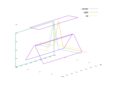
The design refers to a nominal zero reference angle of the motor axis, where the first mirror deflects the beam upward to the middle mirror, that one deflects the beam downward to the last mirror. The picture sketches the three mirrors outlined by magenta quadrangles, three colored rays entering from the right, an exit pupil as a green canvas, and where the rays end up in the exit pupil.

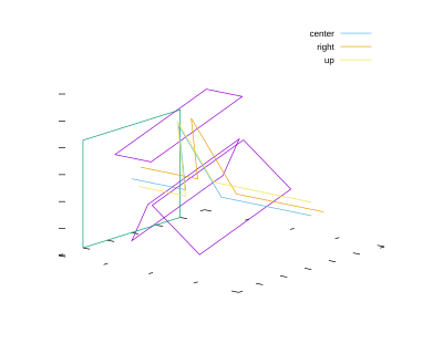
If the mirrors are rotated by 20 degrees, an equivalent ray tracing shows that they rays hit the exit pupil at places rotated by 40 degrees away from the places of the nominal angle.

Matrix optics
The overall effect on a ray that hits the first mirror in the laboratory frame, where x is the horizontal distance to the beam center and y the vertical distance, can be computed as a succession of
- splitting the position into components perpendicular and parallel to the front mirror
- flipping the component in the incidence plane three times to incorporate the reflections from the first, middle and last mirror, which is essentially the implementation of the Fresnel equations for perfect mirrors. This can be written as a single flip because the three incidence planes are the same,
- derotate the position with the inverse of the first split matrix to end up with a representation in the original laboratory frame.
The three matrices act on column vectors from the left, so the product of them shows the first matrix on the right. β+β0 is the motor angle and its offset in the laboratory reference frame:
The interesting point here is that the rotation of the mechanics by the angle β rotates the image by the angle 2β in the laboratory frame. Because the elements flip the image, the determinant of the matrix is negative.
External links
- Brunelli, A.; Bergomi, M.; Dima, M.; Farinato, J.; Magrin, D.; Marafatto, L. (2012). "Tips and tricks for aligning an image derotator". In McLean, Ian S.; Ramsay, Suzanne K.; Takami, Hideki (eds.). Ground-based and Airborne Instrumentation for Astronomy IV. Vol. 8446. pp. 84464L. doi:10.1117/12.926884.
- "NESSI (New Mexico Exoplanet Spectroscopi Survey Instrument)". 2013.
- Guo, Peng; Zhang, Jinqxu; Yang, Fei; Zhang, Yan (2014). Jiang, Wenhan; Cho, Myung K.; Wu, Fan (eds.). The design and analysis of 2m telescope's K Mirror system. 7th International Symposium on Advanced Optical Manufacturing and Testing Technologies: Large Mirrors and Telescopes. Vol. 9280. pp. 92800C. doi:10.1117/12.2069579.
- Baudet, Jeremie; Jolissaint, Laurent; Keskin, Onur; Yesilyaprak, Cahit; Yerli, Sinan K. (2016). Evans, Christopher J.; Simard, Luc; Takami, Hideki (eds.). Design of a derotator for the 4 m DAG telescope. Ground-based and Airborne Instrumentation for Astronomy VI. Vol. 9908. pp. 99085L. doi:10.1117/12.2234392.
- Hedglen, Alexander D.; Close, Laird M.; Males, Jared R.; Durney, Oliver (2018). "Optical field/Pupil rotator with a novel compact K-mirror for MagAO-X". In Close, Laird M.; Schreiber, Laura; Schmidt, Dirk (eds.). Optiocal field/pupil rotator with a novel compact K-mirror for Mag/AO-X. p. 192. doi:10.1117/12.2312346. ISBN 978-1-5106-1959-3.
- Kleint, L. "GREGOR: Derotator manual" (PDF). Archived from the original (PDF) on 2019-02-26. Retrieved 2019-02-25.
