This is an old revision of this page, as edited by MrsSnoozyTurtle (talk | contribs) at 05:29, 3 November 2019 (→Bearings: straight-eight wikilink). The present address (URL) is a permanent link to this revision, which may differ significantly from the current revision.
Revision as of 05:29, 3 November 2019 by MrsSnoozyTurtle (talk | contribs) (→Bearings: straight-eight wikilink)(diff) ← Previous revision | Latest revision (diff) | Newer revision → (diff) For other uses, see Crankshaft (disambiguation).
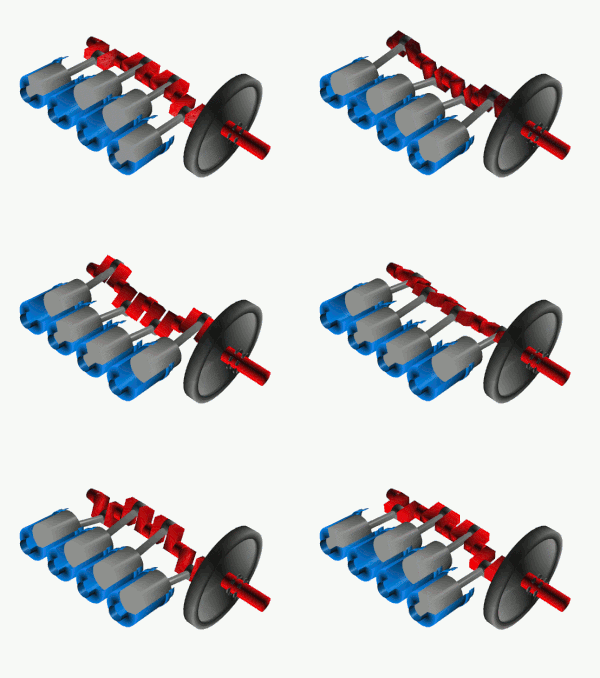
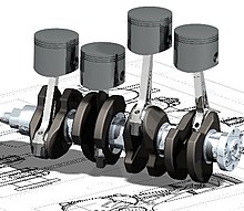
A crankshaft is a rotating shaft which (in conjunction with the connecting rods) converts reciprocating motion of the pistons into rotational motion. Crankshafts are commonly used in internal combustion engines and consist of a series of cranks and crankpins to which the connecting rods are attached.
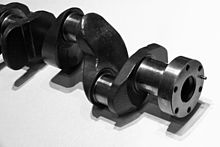
The crankshaft rotates within the engine block through use of main bearings, and the crankpins rotate within the connecting rods using rod bearings. Crankshafts are usually made from metal, with most modern crankshafts being constructed using forged steel.
Origins
Main article: Crank (mechanism)
The predecessor to the crankshaft is the crank— an arm attached to a pivot point, which converts reciprocating motion into the rotation of a shaft. The earliest cranks were hand-operated and appeared in China from 202 BC-220 AD. Hand-operated cranks have also been discovered from the 5th century BC in the Roman Empire.
The first known combination of a crank with a connecting rod is the Hierapolis mill dating to the 3rd century AD in modern-day Turkey. This mill was powered by a water wheel, and used a crank and connecting rod arrangement to move a saw blade back-and-forth.
Some historians credit the invention of the crankshaft to Arab engineer Al-Jazari in the 12th century AD, for his water-raising machines which included a crank and connecting rod system.
A further development was the compound crank design used in a carpenter's brace, with the lower spindle (within the U-shaped section) being equivalent to the crankpin in a crankshaft. The earliest depictions of braces are from Northern Europe in 1420-1430 AD. Soon after, depictions of double-compound cranks with connecting rods began to appear, some of which included a flywheel to get them over the 'dead-spot'.
From the 16th century onwards, evidence of cranks and connecting rods integrated into European machine design becomes abundant in the technological treatises of the period: Agostino Ramelli's The Diverse and Artifactitious Machines of 1588 depicts eighteen examples, a number that rises in the Theatrum Machinarum Novum by Georg Andreas Böckler to 45 different machines.
Design


The crankshaft is supported by the engine block, with the engine's main bearings allowing the crankshaft to rotate within the block. The up-down motion of each piston is transferred to the crankshaft via connecting rods. A flywheel is often attached to the front end of the crankshaft, in order to smoothen the power delivery and reduce torsional vibration.
A crankshaft is subjected to enormous stresses, in some cases more than 8.6 tonnes (19,000 pounds) per cylinder. Crankshafts for single-cylinder engines are usually a simpler design than for engines with multiple cylinders.
Bearings
Main article: Main bearingThe crankshaft is able to rotate in the engine block due to the main bearings. Since the crankshaft is subject to large sideways forces from each cylinder, bearings are located at various points along the crankshaft, not just one at each end. This was a factor in V8 engines replacing straight-eight engines in the 1950s. The long crankshafts of the latter suffered from an unacceptable amount of flex when engine designers began using higher compression ratios and higher engine speeds (RPM). High performance engines often have more main bearings than their lower performance cousins for this reason.
Cross-plane vs flat-plane
Most production V8 engines use crank throws spaced 90° apart, which is called a "cross-plane" configuration (such as the Ford Modular engine and the General Motors LS engine). Several high-performance V8 engines (such as the Ferrari 355) instead use use a "flat-plane" crankshaft with throws spaced 180° apart, essentially resulting in two inline-four engines running in a common crankcase.
Flat-plane engines are usually able to rev higher, however they have more vibration. Flat-plane crankshafts were used on several early V8 engines. See the main article on crossplane crankshafts.
Engine balance
For some engines it is necessary to provide counterweights for the reciprocating mass of each piston and connecting rod to improve engine balance. These are typically cast as part of the crankshaft but, occasionally, are bolt-on pieces.
In 1916, the Hudson Motor Car Company began production of the first engines to use balanced crankshafts, which allowed the engine to run at higher speeds (RPM) than contemporary engines.
Flying arms

In some engines, the crankshaft contains direct links between adjacent crank pins, without the usual intermediate main bearing. These links are called flying arms. This arrangement is sometimes used in V6 and V8 engines, as it enables the engine to be designed with different V angles than what would otherwise be required to create an even firing interval, while still using fewer main bearings than would normally be required with a single piston per crankthrow. This arrangement reduces weight and engine length at the expense of reduced crankshaft rigidity.
Piston stroke
The distance the axis of the crank throws from the axis of the crankshaft determines the stroke length of the engine.
Most modern car engines are classified as "over square" or short-stroke, wherein the stroke is less than the diameter of the cylinder bore. A common way to increase the low-RPM torque of an engine is to increase the stroke, sometimes known as "stroking" the engine. Traditionally, the trade-off for a long-stroke engine was reduced power and increased vibration at high RPM.
Counterweights
Some high performance crankshafts also use heavy-metal counterweights to make the crankshaft more compact. The heavy-metal used is most often a tungsten alloy but depleted uranium has also been used. A cheaper option is to use lead, but compared with tungsten its density is much lower.
Counter-rotating crankshafts
The conventional design for piston engines is where each connecting rod is attached to one crankshaft, with the angle of the connecting rod varying as the piston moves through its stroke. This variation in angle results in lateral forces on the pistons, pushing the pistons against the cylinder wall. This lateral force causes additional friction between the piston and cylinder wall and can cause additional wear on the cylinder wall.
To avoid these lateral forces, each piston can be connected to two crankshafts that are rotating in opposite directions, which cancels out the lateral forces. This arrangement also reduces the requirement for counterweights, reducing the mass of the crankshaft. An early example of a counter-rotating crankshaft arrangement is the 1900-1904 Lanchester Engine Company flat-twin engines.
Construction
| This section needs additional citations for verification. Please help improve this article by adding citations to reliable sources in this section. Unsourced material may be challenged and removed. (October 2019) (Learn how and when to remove this message) |
Forging, casting and machining


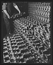
The most common construction methods for crankshafts are forging (usually through roll forging) or casting. Most crankshafts are made in a single piece, however some smaller and larger engines use crankshafts assembled from multiple pieces.
Recently, forging has become the most common construction method for crankshafts, due to their lighter weight, more compact dimensions and better inherent damping. With forged crankshafts, vanadium microalloyed steels are mostly used as these steels can be air cooled after reaching high strengths without additional heat treatment (aside from the surface hardening of the bearing journals). The low alloy content also makes the material cheaper than high alloy steels.
Casting (using cast iron) is today mostly used for crankshafts in cheaper, lower performance engines.
Crankshafts can also be machined out of a billet of steel. These crankshafts tend to be expensive due to the large amount of material that must be removed with lathes and milling machines, the high material cost, and the additional heat treatment required. Since no expensive tooling is needed, this production method is mostly used for low-volume engines. In a machined crankshafts, the fibre flow (local inhomogeneities of the material caused by the casting process) does not follow the shape of the crankshaft, however this is rarely a problem since machined crankshafts often use higher quality steels than forged crankshafts.
Fatigue strength
To improve the fatigue strength, a radius is often rolled at the ends of each main and crankpin bearing. The radius itself reduces the stress in these critical areas, but since the radius in most cases is rolled, this also leaves some compressive residual stress in the surface, which prevents cracks from forming.
Microfinishing is a grinding process to produce a smooth finish on the surface of a metallic object, which is also used to prevent cracks developing from fatigue stress.
Bearing surfaces
Most mass-production crankshafts use induction hardening for the bearing surfaces. Some high performance crankshafts, billet crankshafts in particular, use nitridization instead. For crankshafts that operate on roller bearings, the use of carburization tends to be favored due to the high contact stresses in such situations.
See also
References
- "Definition of CRANKSHAFT". Merriam-Webster Dictionary.
- Ahmad Y Hassan. The Crank-Connecting Rod System in a Continuously Rotating Machine.
- Sally Ganchy, Sarah Gancher (2009), Islam and Science, Medicine, and Technology, The Rosen Publishing Group, p. 41, ISBN 978-1-4358-5066-8
- Donald Hill (2012), The Book of Knowledge of Ingenious Mechanical Devices, page 273, Springer Science + Business Media
- Cite error: The named reference
Hill1979was invoked but never defined (see the help page). - White, Jr. 1962, p. 112 harvnb error: no target: CITEREFWhite,_Jr.1962 (help)
- White, Jr. 1962, p. 113 harvnb error: no target: CITEREFWhite,_Jr.1962 (help)
- White, Jr. 1962, p. 172 harvnb error: no target: CITEREFWhite,_Jr.1962 (help)
- "How to Build Racing Engines: Crankshafts Guide". www.musclecardiy.com. 5 April 2015. Retrieved 27 October 2019.
- Nunney, Malcolm J. (2007). Light and Heavy Vehicle Technology (4th ed.). Elsevier Butterworth-Heinemann. ISBN 978-0-7506-8037-0.
- Andersson BS (1991), Company's perspective in vehicle tribology. In: 18th Leeds-Lyon Symposium (eds D Dowson, CM Taylor and MGodet), Lyon, France, 3-6 September 1991, New York: Elsevier, pp. 503–506
| Internal combustion engine | |
|---|---|
| Part of the Automobile series | |
| Engine block and rotating assembly | |
| Valvetrain and Cylinder head | |
| Forced induction | |
| Fuel system | |
| Ignition | |
| Engine management | |
| Electrical system | |
| Intake system | |
| Exhaust system | |
| Cooling system | |
| Lubrication | |
| Other | |